Charging circuit for an energy storage device and method for charging an energy storage device

a charging circuit and energy storage technology, applied in battery/fuel cell control arrangement, hybrid vehicles, propulsion by capacitors, etc., can solve problems such as breakdown of the entire system, failure of the entire supply string, and drop in performance of the entire energy supply string

Inactive Publication Date: 2016-09-08
ROBERT BOSCH GMBH
View PDF8 Cites 11 Cited by
  • Summary
  • Abstract
  • Description
  • Claims
  • Application Information

AI Technical Summary

Benefits of technology

[0017]By using a half-bridge comprising semiconductor switches as a supply device, it can advantageously be ensured that charging energy can be supplied to the energy storage device in any case because a charging current through the semiconductor switches can selectively be supplied to only those energy supply branches in which the present polarity of the output voltage thereof in combination with the current flow direction of the charging current brings about an energy supply to the battery modules thereof.

Problems solved by technology

The series connection of a plurality of battery modules inherently has the problem that the entire supply string fails if a single battery module fails.
Such a breakdown of the energy supply string can lead to a breakdown of the entire system.
In addition, reduced outputs occurring temporarily or permanently in an individual battery module can lead to drops in performance in the entire energy supply string.
As a result of this division, a BDI is basically not available as a DC voltage source, for example to supply an on-board electrical system of an electric vehicle.
The charging of the energy storage cells is thus not readily possible via a conventional DC voltage source.

Method used


Image

  • Charging circuit for an energy storage device and method for charging an energy storage device
  • Charging circuit for an energy storage device and method for charging an energy storage device
  • Charging circuit for an energy storage device and method for charging an energy storage device

Examples


Embodiment Construction

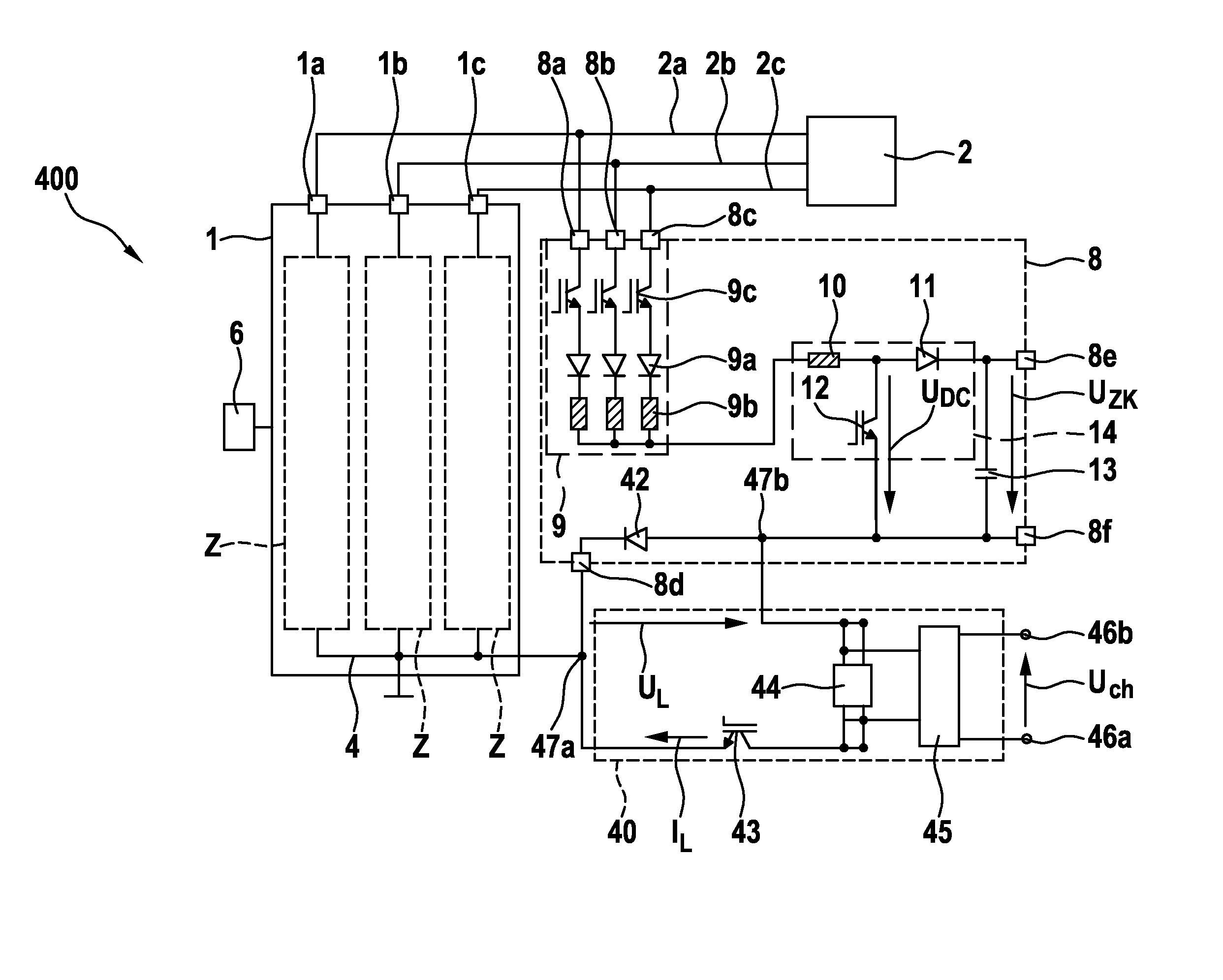
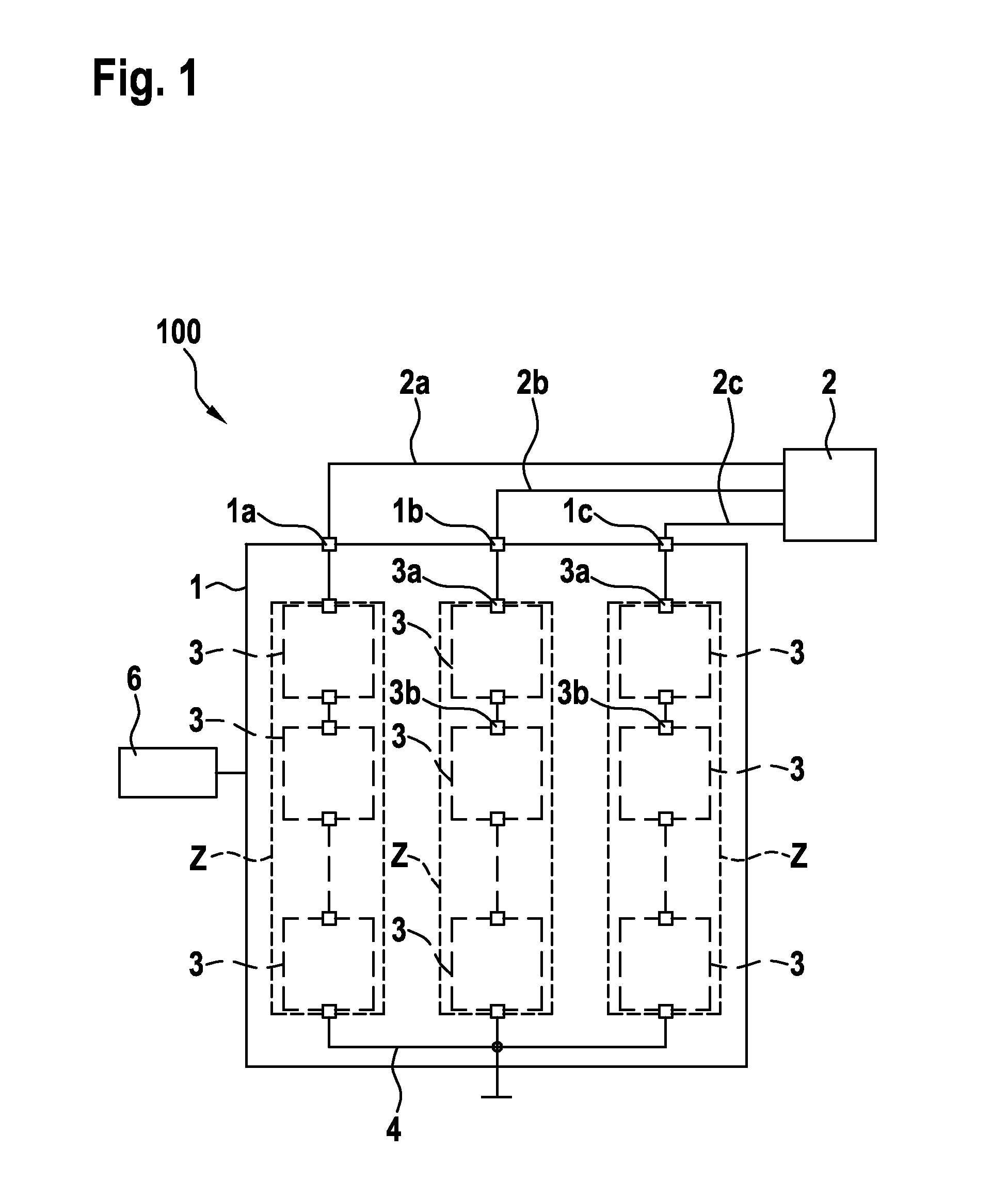
[0042]FIG. 1 shows a schematic depiction of a system 100 comprising an energy storage device 1 for the voltage conversion of DC voltage provided in energy storage modules 3 into an n-phase AC voltage. The energy storage device 1 comprises a multiplicity of energy supply branches Z, of which three are shown by way of example in FIG. 1 and which are suitable for generating a three-phase AC voltage, for example for a three-phase machine. It is, however, clear that any other number of energy supply branches Z can likewise be possible. The energy supply branches Z can have a multiplicity of energy storage modules 3, which are connected in series in the energy supply branches Z. By way of example, three energy storage modules 3 are shown in each case per energy supply branch Z, wherein any other number of energy storage modules 3 can, however, also be possible. The energy storage device 1 has an output connection 1a, 1b and 1c, the connections of which are each connected to phase lines 2a...


PUM


Abstract

The invention relates to a charging circuit for an energy storage device (1), having a multiplicity of energy supply branches (Z) each with a multiplicity of energy storage modules (3) for generating an AC voltage at a multiplicity of output connections (1a, 1b, 1c) of the energy storage device (1). The charging circuit has a first half-bridge circuit (9) having a multiplicity of first supply connections (8a, 8b, 8c) each coupled to one of the output connections (1a, 1b, 1c) of the energy storage device (1), a first supply node (37a; 37b; 47a; 47b) coupled to the first half-bridge circuit (9), a second supply node (37a; 37b; 47a; 47b) coupled to a reference potential rail (4) of the energy storage device (1), a converter inductor (10) connected between the first supply node (37a; 37b; 47a; 47b) and the first half-bridge circuit (9), a diode half-bridge (32) coupled between the first supply node (37a; 37b; 47a) and the second supply node (37a; 37b; 47b), and a supply circuit (35; 44, 45) designed to at least occasionally provide a charging DC voltage (UL) between the first supply node (37a; 37b; 47a; 47b) and the second supply node (37a; 37b; 47a; 47b). In this case, the first half-bridge circuit (9) has a multiplicity of semiconductor switches (9c) each coupled between the first supply node (37a; 37b; 47a; 47b) and one of the multiplicity of first supply connections (8a, 8b, 8c).

Description

BACKGROUND OF THE INVENTION[0001]The invention relates to a charging circuit for an energy storage device and a method for charging an energy storage device, in particular for charging a battery direct inverter with a DC voltage.[0002]It has become apparent that electronic systems, which combine new energy storage technologies with electric drive technology, will increasingly be used in the future in stationary applications, such as, e.g., wind turbines or solar energy systems, as well as in vehicles, such as hybrid or electric vehicles.[0003]The feed of multi-phase current into an electrical machine is usually accomplished by an inverter in the form of a pulse width modulated inverter. To this end, a DC voltage provided by a DC voltage intermediate circuit can be converted into a multi-phase AC voltage, for example a three-phase AC voltage. The DC voltage intermediate circuit is thereby supplied by a string of battery modules connected to one another in series. In order to be able ...

Claims


Application Information

Patent Timeline
Patent Type & Authority Applications(United States)
IPC IPC(8): H02J7/00H02M7/44H02M1/42H02M7/04
CPCH02J7/0013H02J7/0052H02M1/42H02M7/44H02M7/04H02M7/49B60L1/003B60L15/20B60L2210/30H02J1/108Y02T10/92Y02T10/7072Y02T90/14B60L53/14B60L53/22B60L50/40B60L50/62B60L50/51B60L53/24B60L58/18B60L58/21B60L58/20Y02T10/62Y02T10/70Y02T10/64Y02T10/72Y04S10/126H02J7/00Y02E60/00Y02T90/12
Inventor RAPP, HOLGER
Owner ROBERT BOSCH GMBH
Why Eureka
Try Eureka