Tire pressure monitoring device, system and method

a technology of tire pressure monitoring and monitoring device, applied in the direction of measuring device, instrument, way, etc., can solve the problems of halting the motor vehicle, inability to accurately measure, and early tire failur

Inactive Publication Date: 2008-05-15
JONES RUSSELL F
View PDF3 Cites 13 Cited by
  • Summary
  • Abstract
  • Description
  • Claims
  • Application Information

AI Technical Summary

Problems solved by technology

The problems with this technique include the need to halt the motor vehicle before any measurement can be made and the inherent inaccuracy of the measurement, itself.
An under-inflated tire (Prior Art FIG. 1a) is vulnerable to overheating and possibly igniting, as well as “rim bruises,” e.g., if a tire impacts uneven road, a rock, a rut, a pothole, or a curb, the tire has a tendency to flex to an extent such that the tire material will become “pinched” by the rim, thereby leading to early tire failure.
In the case of an over-inflated tire (Prior Art FIG. 1b), by riding on its centerline, uneven stresses are introduced into the tire material, thereby weakening or failing the tire.
Clearly, by the time wear indicators appear, the tire has already been structurally compromised.
Such primitive methods are not conducive to an early diagnosis.
Other, slightly more advanced techniques for land v...

Method used


Image

  • Tire pressure monitoring device, system and method
  • Tire pressure monitoring device, system and method
  • Tire pressure monitoring device, system and method

Examples


Embodiment Construction

,” disclosed, infra.

BRIEF DESCRIPTION OF THE DRAWINGS

[0012]For a better understanding of the present invention, reference is made to the below-referenced accompanying Drawings. Reference numbers refer to the same or equivalent parts of the present invention throughout the several figures of the Drawings.

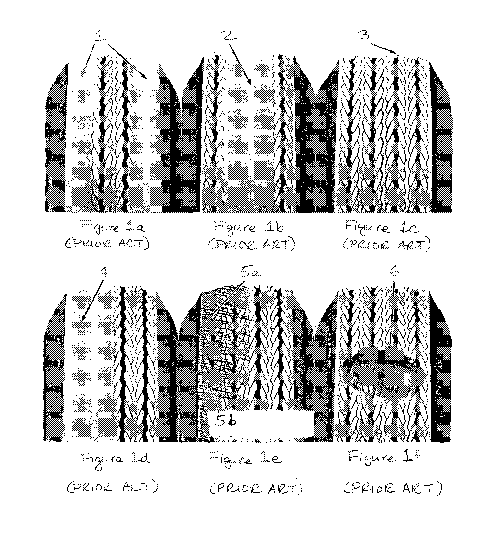
[0013]FIGS. 1a-1f are frontal views of six tires, each tire exemplifying a visual indication of typical wear; in accordance with the prior art “eye-balling” method.

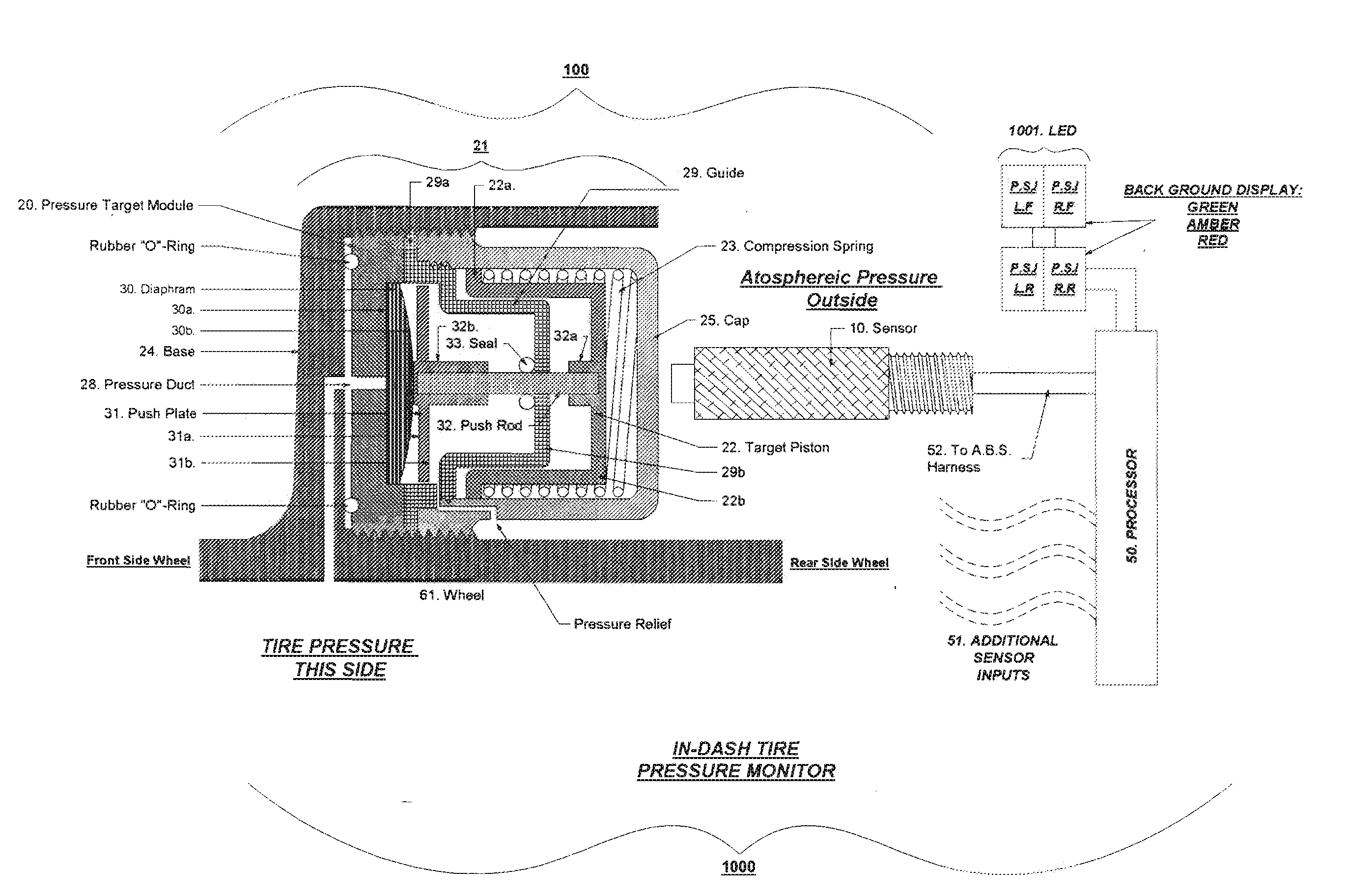
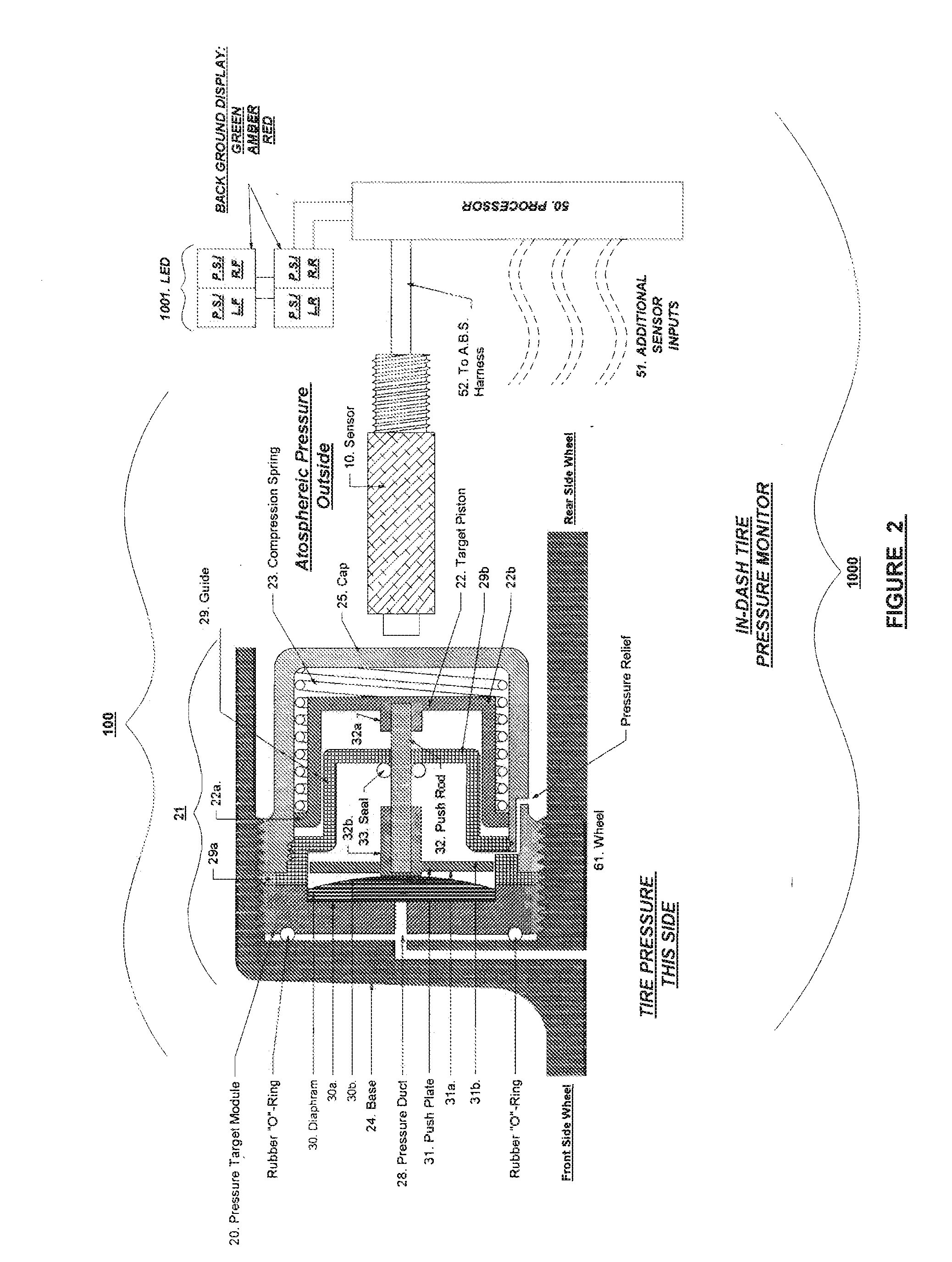
[0014]FIG. 2 is a frontal cross-sectional view of a tire pressure monitoring device, shown in schematic relation to an overall tire pressure monitoring system, showing configuration of the pressure target module applicable for embedding within the inside surface of a wheel or a wheel spoke surface, by example only, in accordance with the present invention.

[0015]FIG. 2a is a frontal cross-sectional view of a tire pressure-monitoring device, shown in schematic relation to an overall tire pressure monitoring system, in accord...


PUM


Abstract

A device, system, and method for monitoring tire pressure of a vehicle, involving a sensor having a structure for carrying a primary current to generate a primary electromagnetic field; and a pressure target module having a structure for inducing a secondary current to generate a secondary electromagnetic field when disposed in a vicinity of the sensor during a revolutionary incident.

Description

TECHNICAL FIELD[0001]The present invention technically relates to tire devices, systems, and methods. More particularly, the present invention technically relates to tire pressure sensing devices, systems, and methods. Even more particularly, the present invention technically relates to automotive and aerospace tire pressure monitoring devices, systems, and methods.BACKGROUND ART[0002]The currently existing art involves manually measuring tire pressure, for land vehicles, using a hand-held tire pressure gauge. The problems with this technique include the need to halt the motor vehicle before any measurement can be made and the inherent inaccuracy of the measurement, itself. Another related art method for assessing tire pressure is the physical inspection or “eye-balling” of the tires, which involves observing, wear indicators while the vehicle is stopped (Prior Art FIGS. 1a-1f). For example, excessive wear at the centerline of the tire 1, i.e., “center tread wear,” indicates over-pr...

Claims


Application Information

Patent Timeline
IPC IPC(8): G01M17/02
CPCG01M17/02
Inventor JONES, RUSSELL F.
Owner JONES RUSSELL F
Why Eureka
Try Eureka