Filtering matrix structure, associated image sensor and 3D mapping device
Inactive Publication Date: 2012-04-12
COMMISSARIAT A LENERGIE ATOMIQUE ET AUX ENERGIES ALTERNATIVES
View PDF3 Cites 43 Cited by
Summary
Abstract
Description
Claims
Application Information
AI Technical Summary
This helps you quickly interpret patents by identifying the three key elements:
Problems solved by technology
Method used
Benefits of technology
Problems solved by technology
One of the important problems to be solved for an image sensor is that of obtaining colors.
A drawback of this sensor however is its impossibility of filtering infrared.
This pixel size then poses a problem when the rays arrive with strong incidence at the surface of the sensor (image edge or strongly open objective).
This phenomenon therefore consi
Method used
Image
Click on the blue label to locate the original text in one second.
Reading with bidirectional positioning of images and text.
Examples
first embodiment
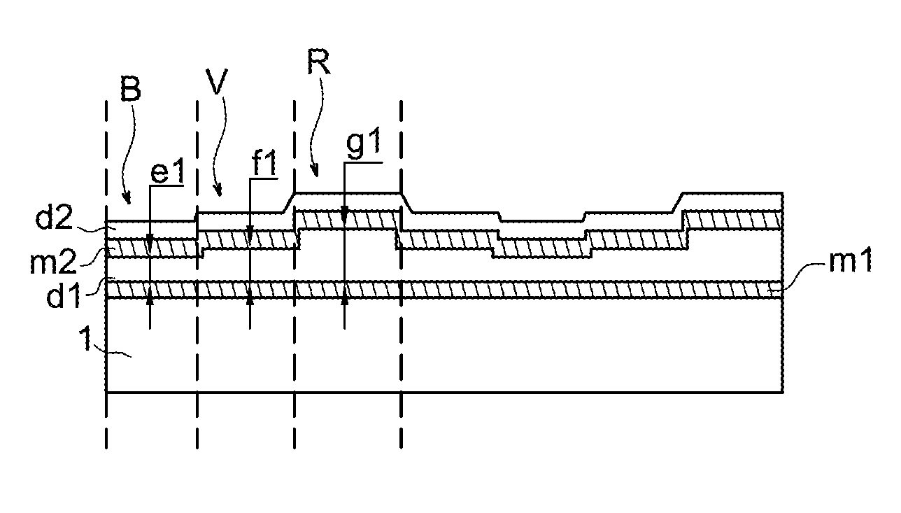
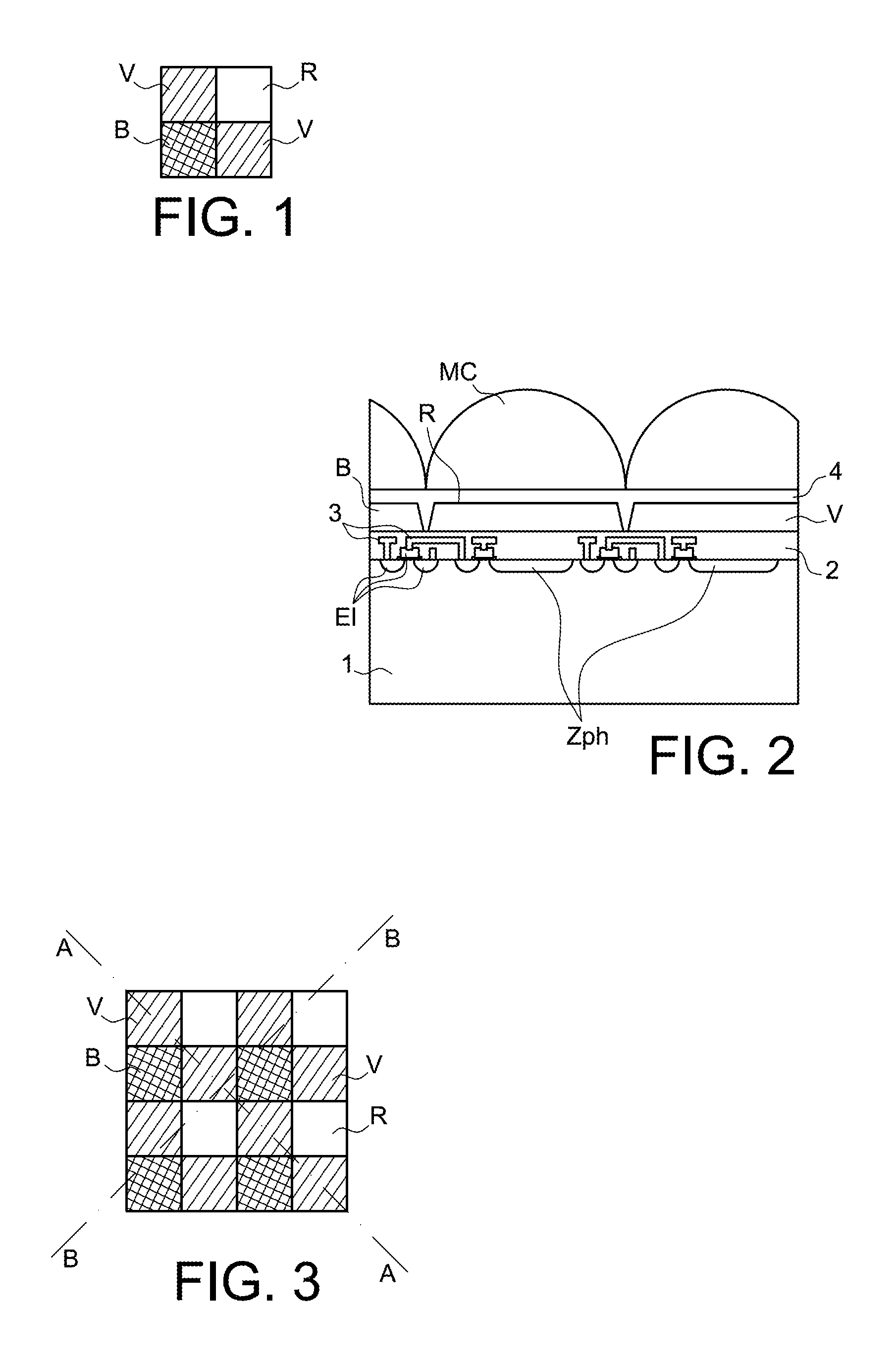
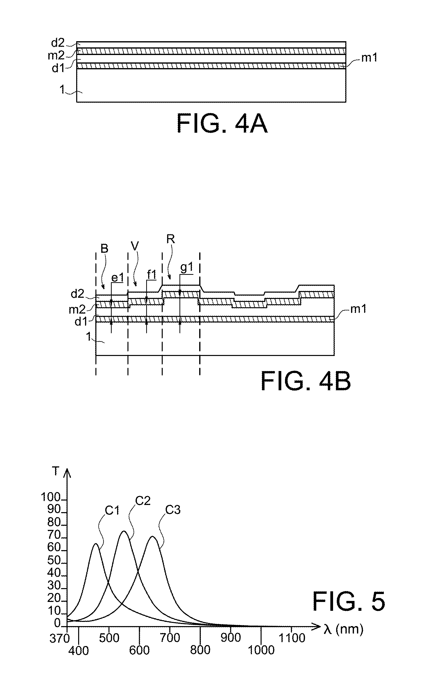
[0057]FIGS. 4A and 4B illustrate sectional views, along two different axes, of an optical filtering matrix structure according to the invention described in patent application Ser. No. 12 / 373,832. With reference to FIG. 3, FIG. 4A is a sectional view along the axis AA of FIG. 3 and FIG. 4B is the sectional view along the axis BB of FIG. 3. The AA axis diagonally cuts the green optical filters V. The BB axis is an axis perpendicular to the AA axis and cuts, outside the diagonals, successive blue B, green V, red R, green V, blue B, green V, red R, etc. optical filters.
[0058]The image sensor comprises a photosensitive semiconducting element 1, for example silicon, on which a first metal layer m1, a first transparent layer d1, a second metal layer m2 and a second transparent layer d2 are successively laid. The metal used for producing the metal layers m1 and m2 is silver (Ag) for example and the material used for producing the transparent layers d1 and d2 is a dielectric for example, wh...
second embodiment
[0066]FIGS. 6A and 6B illustrate sectional views, along two different axes of an optical filtering matrix structure according to the invention described in patent application Ser. No. 12 / 373,832. With reference to FIG. 3, FIG. 6A is a sectional view along the AA axis and FIG. 6B is a sectional view along the BB axis.
[0067]The image sensor comprises a photosensitive semiconducting element 1, for example silicon, on which three metal layers m1, m2, m3 and three transparent layers d1, d2, d3 are alternately laid, the metal layer m1 being in contact with the semiconducting element 1. The metal layers m1-m3 are in silver (Ag) for example, and the transparent layers d1-d3 are in titanium dioxide (TiO2) for example.
[0068]The layers d1 and d2 are adjustment layers, of which the changes in thickness set the different transmission wavelengths of the filter, all the other layers having a constant thickness. An overthickness resulting from a change in thickness of the layer d1 coincides with an...
PUM
Abstract
Filtering matrix structure comprising at least three color filters and a plurality of near Infrared filters, each one of the color filters and the near Infrared filters having an optimum transmission frequency, wherein the filtering matrix structure is made of n metal layers (m1, m2, m3) and n substantially transparent layers (d1, d2, d3) which alternate between a first metal layer (m1) and an nth substantially transparent layer (d3), each of the n metal layers (m1, m2, m3) having a constant thickness and at least one substantially transparent layer having a variable thickness which sets the optimum transmission frequency of each color filter and each near Infrared filter, n being an integer larger than or equal to 2.
Application to 3D mapping and imaging.
Description
TECHNICAL FIELD AND PRIOR ART[0001]The present invention is a continuation-in-part application of patent application Ser. No. 12 / 373,832 filed on Jan. 14, 2009.[0002]The invention relates to a filtering matrix structure.[0003]The invention also relates to an image sensor which comprises a filtering matrix structure according to the invention and to a three-dimensional (3D) mapping and imaging device intended to generate a 3D profile of the surface of an object.[0004]The invention finds a particular advantageous application for producing image sensors and 3D mapping and imaging devices of small size.[0005]Obtaining images by an electronic sensor is in full development. The demand for simplification of the production of the sensors continues to be very strong. Charge coupled devices, more commonly called CCD sensors, are gradually replaced with active pixel sensors in CMOS technology, more commonly called CMOS APS (Active Pixel Sensor) sensors.[0006]One of the important problems to be...
Claims
Application Information
Patent Timeline
Application Date:The date an application was filed.
Publication Date:The date a patent or application was officially published.
First Publication Date:The earliest publication date of a patent with the same application number.
Issue Date:Publication date of the patent grant document.
PCT Entry Date:The Entry date of PCT National Phase.
Estimated Expiry Date:The statutory expiry date of a patent right according to the Patent Law, and it is the longest term of protection that the patent right can achieve without the termination of the patent right due to other reasons(Term extension factor has been taken into account ).
Invalid Date:Actual expiry date is based on effective date or publication date of legal transaction data of invalid patent.