Image Reading Apparatus
a technology of image reading and glass plate, applied in the field of image reading apparatus, can solve the problems of increasing the total manufacturing cost, the glass plate bonded by the adhesive tape is not easily peeled from the case, and the biasing force of the biasing unit, which acts on the glass plate, cannot be made large, so as to achieve the effect of stable biasing for
- Summary
- Abstract
- Description
- Claims
- Application Information
AI Technical Summary
Benefits of technology
Problems solved by technology
Method used
Image
Examples
first embodiment
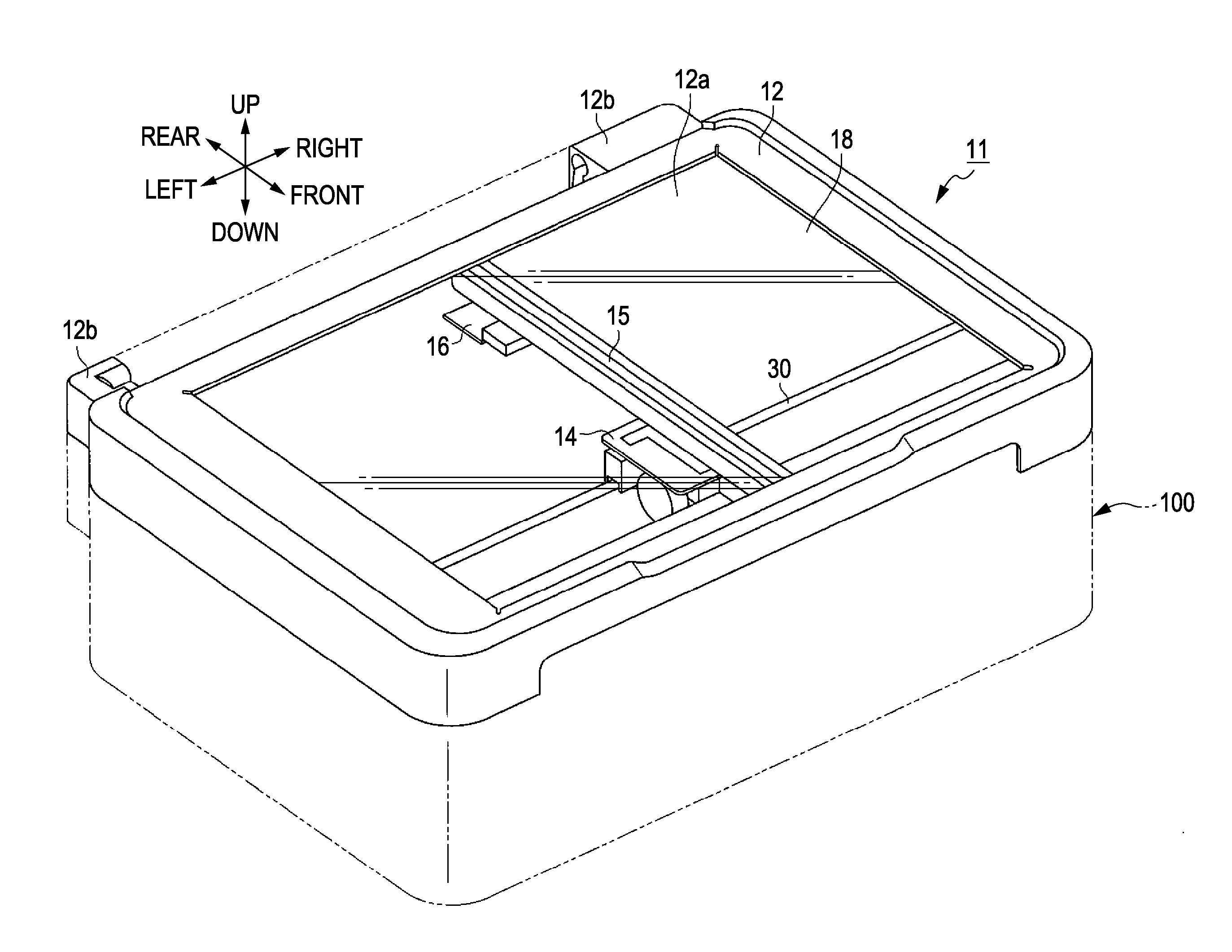
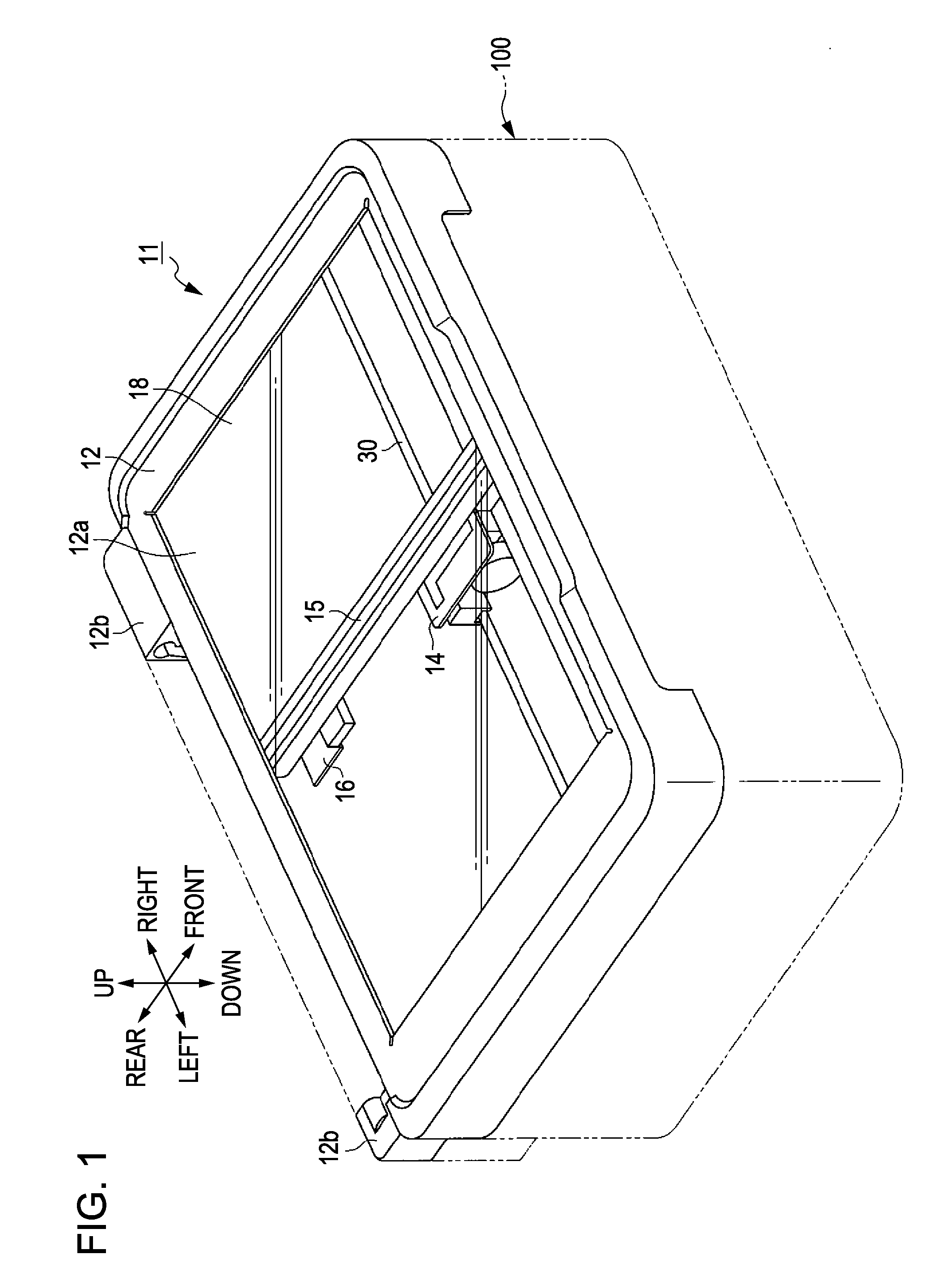
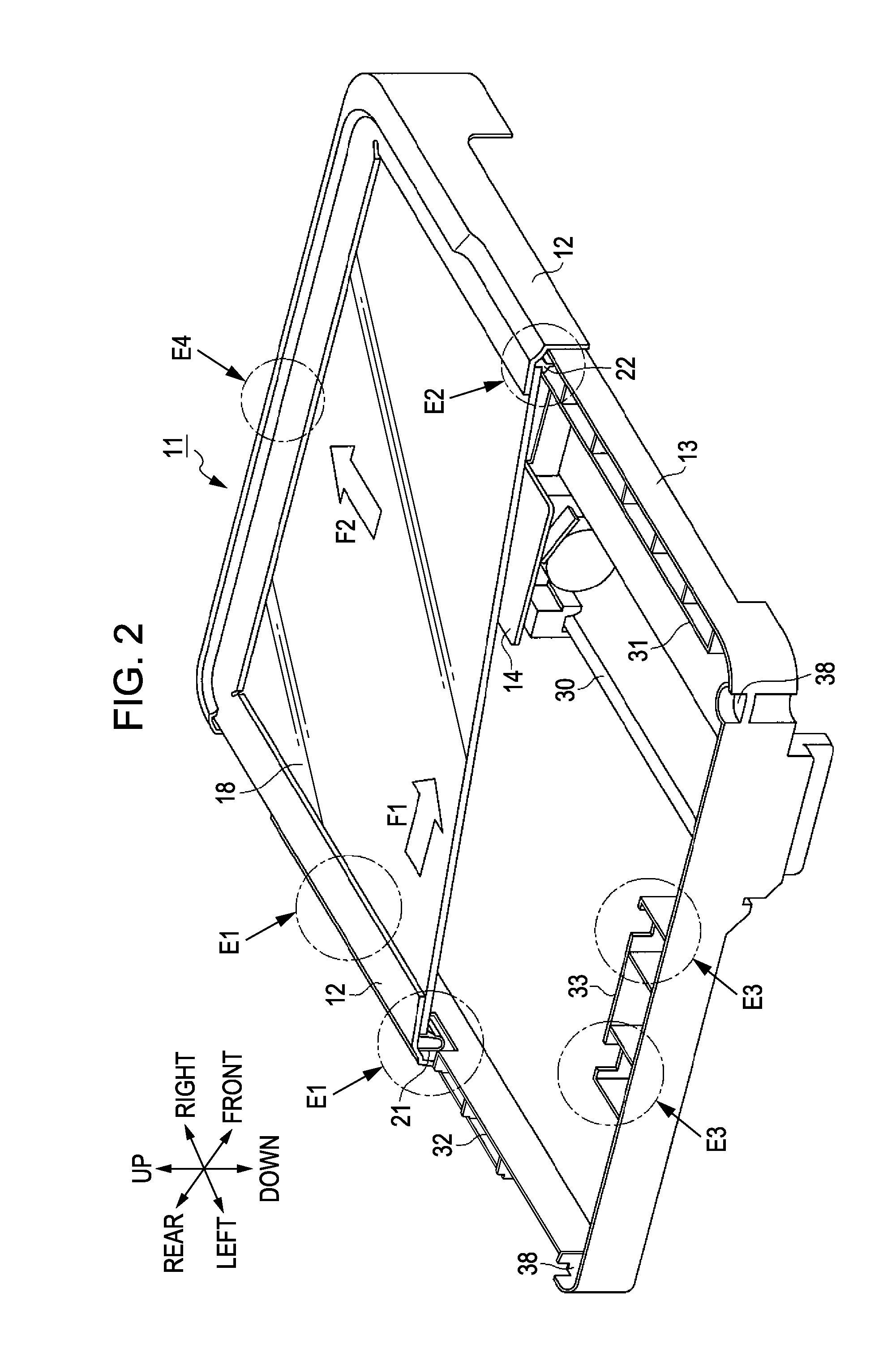
[0027]Hereinafter, an embodiment in which the invention is embodied in a scanner as an example of an image reading apparatus is described with reference to FIG. 1 through FIG. 5B. It is to be noted that “front-rear direction”, “up-down direction” and “right-left direction” used in the following description indicate “front-rear direction”, “up-down direction” and “right-left direction” indicated by arrows in each of the drawings, respectively, unless otherwise specified. Further, in this case, the “up-down direction” corresponds to a vertical direction, the “right-left direction” corresponds to a direction in which an image reading unit (line sensor) constituting the scanner moves, and the “front-rear direction” corresponds to a reading width direction of the image reading unit (line sensor).
[0028]As illustrated in FIG. 1, a scanner 11 includes an upper case 12 as a first housing, and a lower case 13 (see, FIG. 2) as a second housing. The upper case 12 forms an outer frame of the sca...
second embodiment
[0054]Next, the second embodiment is described. This embodiment is an embodiment in which the positioning members 21, 23 are provided so as to be separated from the upper case 12 and have shapes other than the hook shapes. The embodiment is different from the above first embodiment only in the configuration relating to the positioning members. Accordingly, hereinafter, only the positioning members are described and other configurations are denoted with the same reference numerals and description thereof is not repeated.
[0055]The embodiment is described with reference to FIGS. 6A and 6B. It is to be noted that FIGS. 6A and 6B correspond to FIGS. 5A and 5B in the above first embodiment. FIG. 6A illustrates a state where the glass plate 18 is temporarily fixed and FIG. 6B illustrates a state where the glass plate 18 is permanently fixed.
[0056]As illustrated in FIG. 6A, each positioning member 40 is constituted by a plurality of members which are separated from the upper case 12. That i...
PUM
 Abstract
Description
Claims
Application Information
 - R&D
- Intellectual Property
- Life Sciences
- Materials
- Tech Scout
- Unparalleled Data Quality
- Higher Quality Content
- 60% Fewer Hallucinations
Browse by: Latest US Patents, China's latest patents, Technical Efficacy Thesaurus, Application Domain, Technology Topic, Popular Technical Reports.
© 2025 PatSnap. All rights reserved.Legal|Privacy policy|Modern Slavery Act Transparency Statement|Sitemap|About US| Contact US: help@patsnap.com


