Exhaust geometry for particle grouping

Active Publication Date: 2012-04-19
PEMRED
View PDF5 Cites 0 Cited by
  • Summary
  • Abstract
  • Description
  • Claims
  • Application Information

AI Technical Summary

Benefits of technology

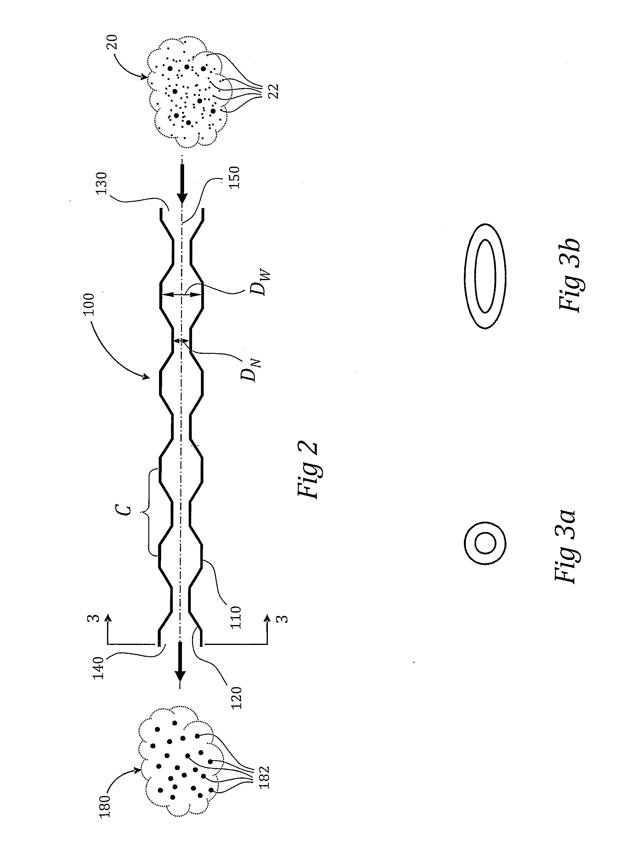
[0008]When gas containing inhalable particles that enters the exhaust pipe through the first open end and flows out of the exhaust pipe through the second open end, a substantial amount of the inhalable parti

Problems solved by technology

Particles, having a size ranging from nanometers to micrometers (herein after referred to as “submicron particles”), impose risk to the health and to the environment.
Furthermore, the stay time of smaller size particles in

Method used


Image

  • Exhaust geometry for particle grouping
  • Exhaust geometry for particle grouping
  • Exhaust geometry for particle grouping

Examples


Example

Example

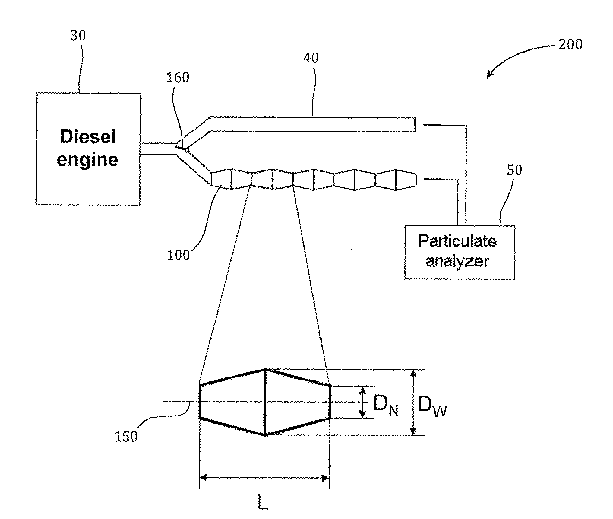
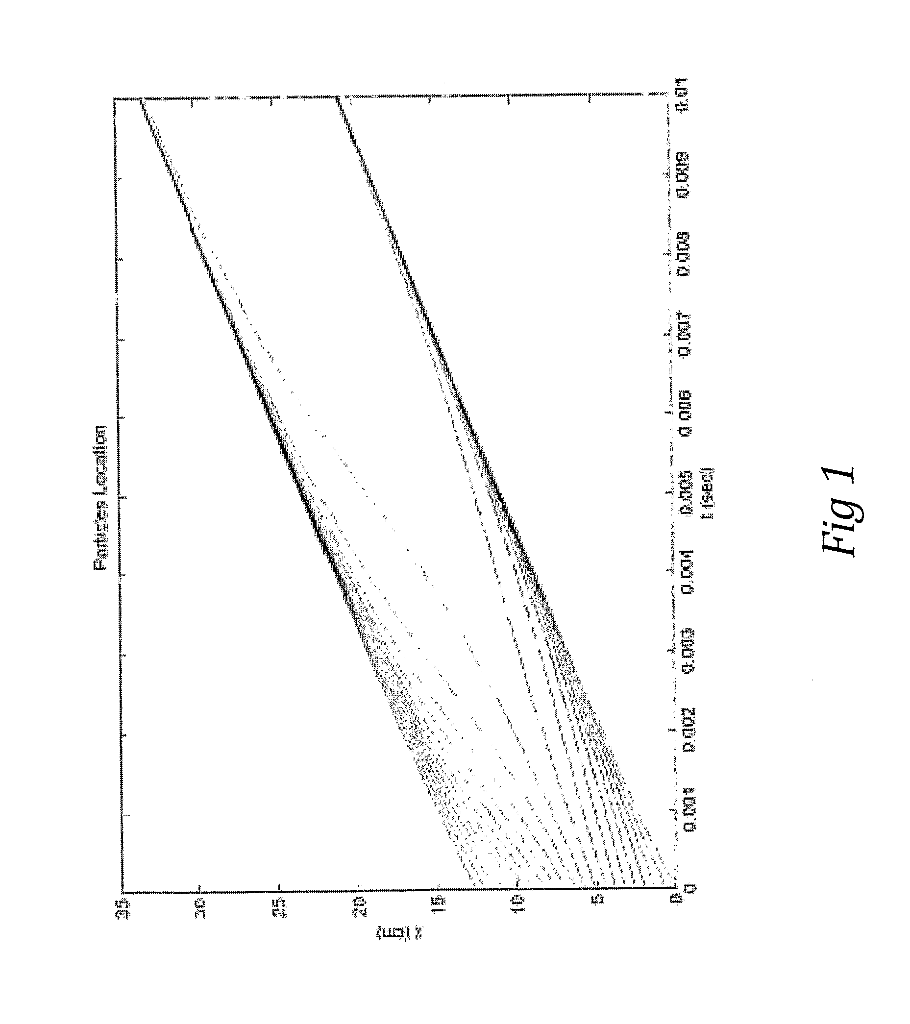
[0038]An experimental setup is shown in FIG. 5. The exhaust of a Diesel engine 30 is operatively attached, in parallel, to two exhaust pipes: a) straight conventional steel pipe 40, and b) exhaust pipe 100, having 6 cycles C. Both pipes 40 and 100 are 80 cm long and have the same flow rate. At the outlet of each pipe measurement apparatus 50 are used to measure the size distribution of the particles. A particulate analyzer 50 is used to detect and measure particles in the 300 nm to 2 μm diameter range. Pipe selector 160 is used to select the exhaust pipe being under test.

The experimental engine specifications are as follows:

Engine modelMitsubishi S3L engineEngine typeThree-cylinder, 4-stroke, compression-ignited, air-cooled engineCylinder stroke / borestroke / bore 78.5 / 78 mmDisplacement volume1,125 cm3Rated power:11.8 kW at 1,500 rev / min

[0039]In each test, the engine was operated under a set of operation conditions (engine speed and engine load). The engine was run under the spe...


PUM


Abstract

An exhaust pipe (100) for a fuel burning engine including a hollow body, the body having an internal surface (120), an external surface (110), a first open end (130), a second open end (140) and a longitudinal axis, wherein the internal surface (120) is shaped to form standing cyclic wave geometry having at least 2 cycles (c). When gas containing inhalable particles (22) enters the exhaust pipe (100) through the first open end (130) and flows out of the exhaust pipe (100) through the second open end (140), a substantial amount of inhalable particles (22) are grouped to form filterable particles (182).

Description

RELATED APPLICATION[0001]The present application claims the benefit of U.S. provisional application 61 / 164,477 filed on Mar. 30, 2009, the disclosure of which is incorporated herein by reference.FIELD OF THE INVENTION[0002]The present invention relates to clustering of small particles and more particularly to grouping of submicron particles in a pipe having a standing wave like geometry.BACKGROUND AND PRIOR ART[0003]There is a major health and environmental concern regarding emitted particles from vehicle exhaust pipes, in particularly from Diesel engines. Particles, having a size ranging from nanometers to micrometers (herein after referred to as “submicron particles”), impose risk to the health and to the environment. Since the submicron particles are small in size, it is easier for the submicron particles to penetrate the respiratory system. Furthermore, the stay time of smaller size particles in the air is much longer. For example, a particle of 0.1 micron will stay about 100 ti...

Claims


Application Information

Patent Timeline
IPC IPC(8): F01N3/037
CPCB01D51/06B01D2258/012Y02T10/20F01N3/033F01N3/037F01N3/021Y02T10/12F01N13/08
Inventor KATOSHEVSKI, DAVIDRUZAL, MICHALSHER, ERAN
Owner PEMRED
Why Eureka
Try Eureka