Method for cleaning two filters of a suction device for cleaning purposes and suction device for performing the method

a technology of suction device and filter, which is applied in the direction of cleaning filter means, filtration separation, separation processes, etc., can solve the problems of reducing the suction power of the vacuum cleaner, the pressure rise in the dirt collection container, and the disadvantage of both the external air entering the dirt collection container via the open external air inlet and the filter to be cleaned. , to achieve the effect of simple construction simple design of the suction device, and simple design of the su

Active Publication Date: 2012-04-19
ALFRED KARCHER GMBH & CO KG
View PDF1 Cites 19 Cited by
  • Summary
  • Abstract
  • Description
  • Claims
  • Application Information

AI Technical Summary

Benefits of technology

[0029]It is expedient for the first suction line and the second suction line to be permanently sealed off relative to each other. This enables a simple design of the suction device. In particular, it is not necessary to provide active elements such as, for example, valves which, when cleaning the first filter and the second filter, close a fluidic connection existing between the first suction line and the second suction line during normal suction operation.
[0030]A constructionally simple, permanent sealing-off of the suction lines relative to each other can be achieved by the first suction line and the second suction line being configured as suction channels that are spatially separated from each other.
[0031]The suction device preferably comprises a housing with a first housing part, which at least partially forms the first suction line and / or the second suction line. This enables a constructionally simple design of the suction device. The housing of the suction device and, in particular, its first housing part may, for example, be of one-piece configuration and be made of a plastic material. It is possible that the first housing part forms at least partially walls of the first suction line and / or the second suction line.
[0032]The suction device preferably comprises a housing with a second housing part, which at least partially forms a wall of at least one external air channel, which opens via the first external air inlet into the first suction line and / or via the second external air inlet into the second suction line. This enables a simple constructional design of the suction device. The second housing part, which, for example, is of one-piece configuration and may be formed by a molded plastic part, can be arranged on the remaining housing of the suction device in such a way that an external air channel is defined between the remaining housing and the second housing part. The second housing part forms at least partially a wall of the external air channel through which external air can flow into the first suction line when the first closing valve is open and external air can flow into the second suction line when the second closing valve is open.
[0033]It is advantageous for the first closing valve and / or the second closing valve to be held on the second housing part, which is transferable from an operating position in which the second housing part covers the first filter and / or the second filter to a maintenance position in which the first filter and / or the second filter are freely accessible, and vice versa. This enables easy maintenance of the suction device. It may occasionally be necessary to exchange the first filter and / or the second filter. With the present embodiment, this may be done by the second housing part being transferred together with the first closing valve and / or the second closing valve held thereon from the operating position to the maintenance position, so that the first filter and / or the second filter are freely accessible to a user. After the appropriate filter has been exchanged, the second housing part can be transferred back to the operating position again and suction operation continued.

Problems solved by technology

During continuous suction operation, particles of dirt may settle on the filters and clog these, which results in a rise in the pressure in the dirt collection container and, consequently, in reduced suction power of the vacuum cleaner.
In the method described in US 2005 / 0011036 A1, it has proven disadvantageous that both the external air that has entered the dirt collection container via the open external air inlet and the filter to be cleaned and the suction air drawn in through the suction hose have to be sucked off by the suction unit.
When external air flows into the dirt collection container, this brings about an uncontrollable rise in pressure in it.
In practice, this may result in the negative pressure provided by the vacuum cleaner at the free end of the suction hose no longer being adequate to suck in suction material.
This problem occurs, in particular, with suction hoses having a relatively large diameter, in particular, larger than 40 mm and, for example, 60 mm.
Particularly large suction cross sections of the suction inlet are present in suction devices in the form of vacuum sweepers, in which the uncontrollable rise in pressure in the dirt collection container has also proven disadvantageous.

Method used


Image

  • Method for cleaning two filters of a suction device for cleaning purposes and suction device for performing the method
  • Method for cleaning two filters of a suction device for cleaning purposes and suction device for performing the method
  • Method for cleaning two filters of a suction device for cleaning purposes and suction device for performing the method

Examples


Embodiment Construction

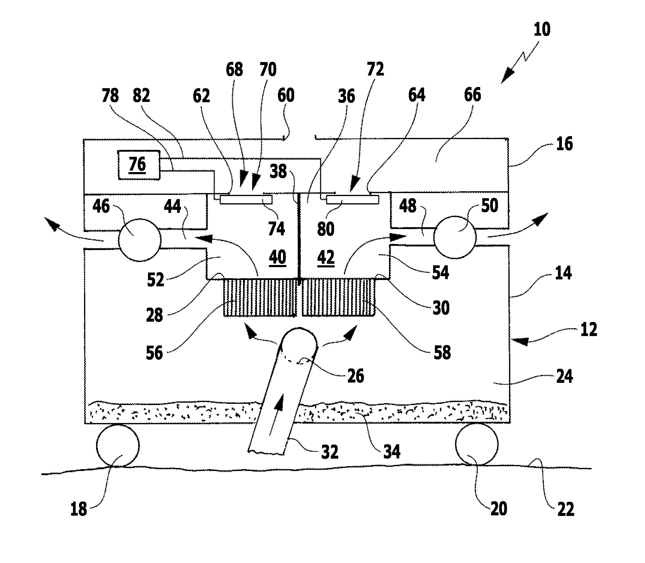
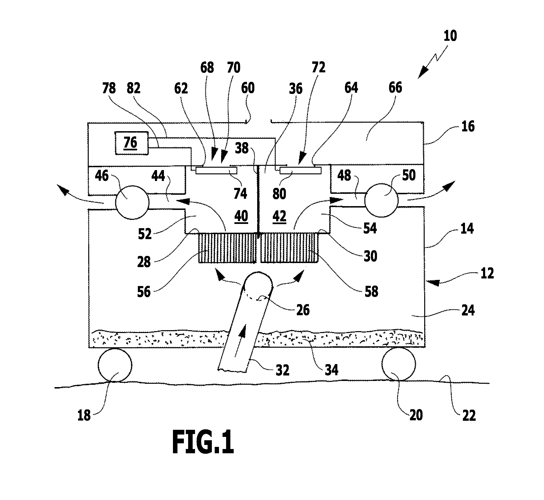
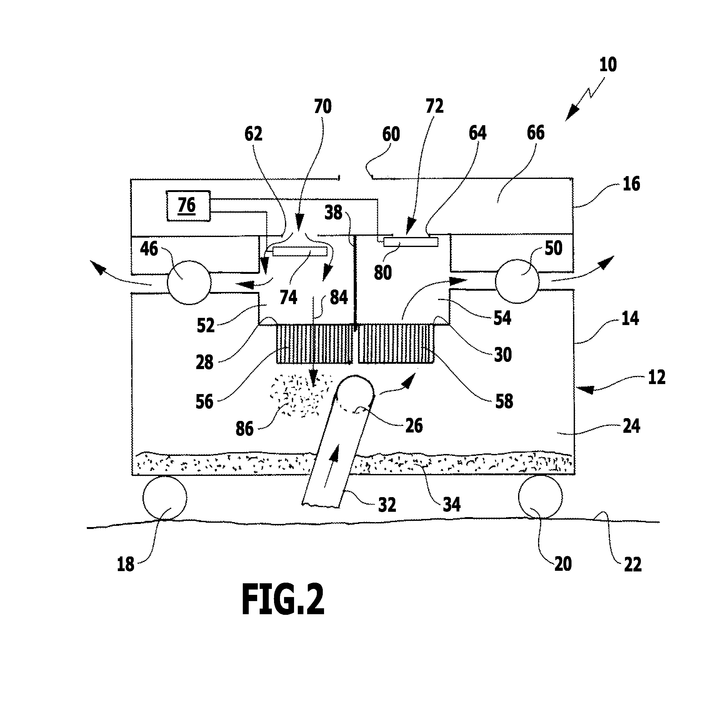
[0046]A first preferred embodiment of a suction device in accordance with the invention in the form of a vacuum cleaner is represented diagrammatically in FIGS. 1 to 3 and denoted therein by reference numeral 10. The vacuum cleaner 10 comprises a housing 12 with a lower housing part 14 and an upper housing part 16 fitted thereon. Rollers 18 and 20 serving to move the vacuum cleaner 10 on a set-down surface 22 are held on the lower housing part 14.

[0047]The lower housing part 14 is configured as a hollow body and forms a dirt collection container 24 of the vacuum cleaner 10 with a suction inlet 26 and a first suction outlet 28 and a second suction outlet 30, which are each in the form of a through-opening of the lower housing part 14. Detachably connected to the suction inlet 26 is a suction hose 32, to whose free end, facing away from the dirt collection container 24 and not shown in the drawings, there may be connected, in a known manner and, therefore, not explained in greater det...


PUM

PropertyMeasurementUnit
diameteraaaaaaaaaa
diameteraaaaaaaaaa
pressureaaaaaaaaaa

Abstract

A method for cleaning first and second filters of a suction device for cleaning purposes is provided. The suction device has a dirt collection container with a suction inlet. The dirt collection container is subjected to negative pressure via first and second suction lines, respectively, following the first and second filters. First and second closing valves close first and second external air inlets, respectively, into the first and second suction lines. For cleaning the filters, the closing valves are opened, subjecting the filters to external air on the clean space side. The dirt collection container is subjected to negative pressure via the first suction line and first filter by a first suction unit and via the second suction line and second filter by a second suction unit. The suction lines are sealed off relative to each other on the clean space side at least during the cleaning of the filters.

Description

[0001]This application is a continuation of international application number PCT / EP2009 / 054851 filed on Apr. 22, 2009.[0002]The present disclosure relates to the subject matter disclosed in international application number PCT / EP2009 / 054851 of Apr. 22, 2009, which is incorporated herein by reference in its entirety and for all purposes.BACKGROUND OF THE INVENTION [0003]The invention relates to a method for cleaning a first filter and a second filter of a suction device for cleaning purposes, which comprises a dirt collection container with a suction inlet, wherein the dirt collection container is subjected to negative pressure via the first filter and the second filter and a first suction line and a second suction line, respectively, following the first filter and the second filter, wherein a first closing valve and a second closing valve close a first external air inlet and a second external air inlet, respectively, into the first suction line and the second suction line, respectiv...

Claims


Application Information

Patent Timeline
Patent Type & Authority Applications(United States)
IPC IPC(8): A47L9/20A47L9/10A47L9/28B08B5/04
CPCB01D46/0067B01D46/46B01D46/04B01D46/70
Inventor RENTSCHLER, WERNERENGELHARDT, RAINERFRANK, JUERGENECKSTEIN, DANIEL
Owner ALFRED KARCHER GMBH & CO KG
Why Eureka
Try Eureka