Power transfer switch

a power transfer switch and switch technology, applied in the direction of switch power arrangement, high-tension/heavy-dress switch, snap-action arrangement, etc., can solve the problems of excessive rotation of cross bar b>53/b>, and contact pressure to be applied to the contact poin

Active Publication Date: 2012-04-19
AICHI ELECTRIC WORKS
View PDF8 Cites 12 Cited by
  • Summary
  • Abstract
  • Description
  • Claims
  • Application Information

AI Technical Summary

Benefits of technology

[0011]The power transfer switch according to the present invention has the structure in which the cross bar and the movable contact are elastically held by means of the compression spring. The rotating angle of the cross bar is set to be greater than the rotating allowable angle of the movable contact between the left and right fixed contacts so that one of the protruded pieces of the cross bar is rotated excessively while pressing only one of the step portions of the movable contact also after the movable contact comes into contact with the fixed contact. At this time, the compression spring disposed on the central axis of the movable contact presses the movable contact in order to return the other protruded piece floating from the step portion into an o

Problems solved by technology

However, the cross bar 53 is further rotated excessively by a certain angle.
For

Method used


Image

  • Power transfer switch
  • Power transfer switch
  • Power transfer switch

Examples


Embodiment Construction

[0018]An embodiment according to the present invention will be described below in detail.

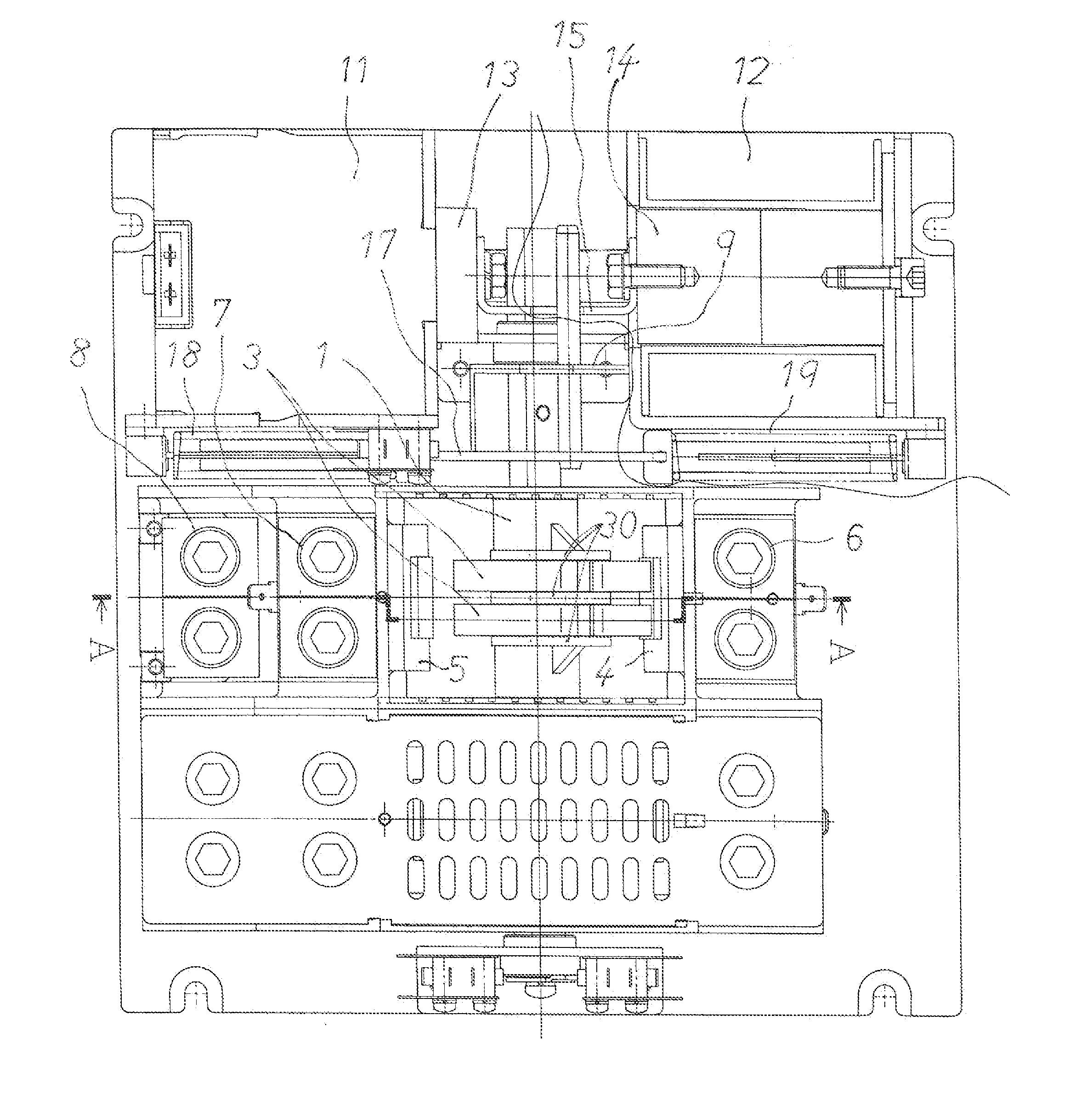
[0019]In FIGS. 3 and 4, 1 denotes a cross bar having a non-circular cross-section and supported on a body rotatably in a left and right direction, 2 denotes a toggle mechanism for rotating the cross bar 1 in any of leftward and rightward directions, 3 denotes a movable contact supported on the cross bar 1, 4 denotes a fixed contact on a right side, and 5 denotes a fixed contact on a left side. The fixed contact 4 on the right side is connected to a power terminal 6 on the right side and the fixed contact 5 on the left side is connected to a power terminal 7 on the left side. Moreover, the movable contact 3 is connected to a load terminal 8.

[0020]For example, the power terminal 6 on the right side is connected to a commercial power source and the power terminal 7 on the left side is connected to an emergency power source. The movable contact 3 is always caused to come into contact with the fixed ...


PUM


Abstract

A power transfer switch in which a cross bar including a movable contact is rotated to come into contact with one of fixed contacts disposed on left and right sides of the cross bar. The cross bar has a non-circular cross-section including a protruded piece on left and right, and a rotating angle thereof is greater than a rotating allowable angle of the movable contact between the fixed contacts. A through hole into which the cross bar is inserted with play is formed on a base portion of the movable contact, and a step portion for receiving the protruded piece of the cross bar and a spring housing portion extended in a direction of a central axis of the movable contact are formed in the through hole. A compression spring is accommodated in the spring housing portion to cause the cross bar to elastically hold the movable contact.

Description

TECHNICAL FIELD[0001]The present invention relates to a power transfer switch which changes over a power source from a commercial power to another power such as an emergency power when a power failure occurs in the commercial power that is connected to a load, and is used for automatically changing over the power source into the commercial power in a power return of the commercial power.BACKGROUND OF THE INVENTION[0002]A power transfer switch is an apparatus for changing over a plurality of power sources to supply an electricity to a load, and is widely used in home or facilities provided with an emergency power (a preliminary power source) such as a power generator for taking a countermeasure against the power failure. In the change-over of the power source, a cross bar is rotated to cause a movable contact held on the cross bar to come into contact with a fixed contact on the opposite side, thereby changing over the power source.[0003]It is desirable to change over the power sourc...

Claims


Application Information

Patent Timeline
IPC IPC(8): H01H5/06
CPCH01H1/225H01H3/28H01H2300/018H01H21/42H01H5/06H01H31/28H01H33/40H01H33/42
Inventor YOSHIDA, KATSUHIROITO, KAZUTOSHI
Owner AICHI ELECTRIC WORKS
Why Eureka
Try Eureka