
Oil reservoir comprising an oil filter

a technology of oil reservoir and oil filter, which is applied in the direction of separation process, liquid degasification, filtration separation, etc., can solve the problems of motor vehicle units failing, affecting the functionality of cooling system, and oil reservoirs often not equipped with oil filters, etc., and achieves the effect of simple design

Active Publication Date: 2012-04-19
ROBERT BOSCH GMBH +1
View PDF4 Cites 11 Cited by
  • Summary
  • Abstract
  • Description
  • Claims
  • Application Information

AI Technical Summary

Benefits of technology

[0006]It is the object of the invention to provide an oil reservoir which comprises an oil filter and which has a simple design and yet prevents air bubbles from making their way into the circuit of a hydraulic system together with the oil taken in from the reservoir.
[0009]The oil reservoir according to the invention therefore comprises an integrated oil filter, however which does not require separate encapsulation because of the guidance track formed for the oil in the reservoir and the resulting ability to effectively separate air that may be present in the oil. In this way, a simple design for the oil reservoir is achieved, which at the same time serves as an oil filter and also takes into account the need for suppressing the entrance of air in the form of air bubbles present in the oil into the hydraulic circuit.
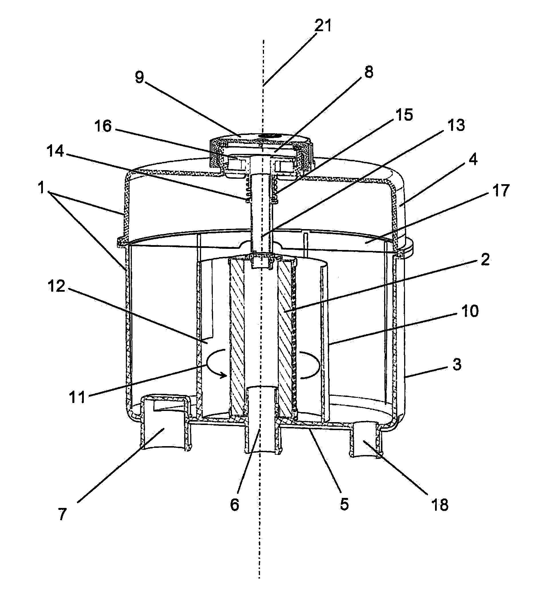
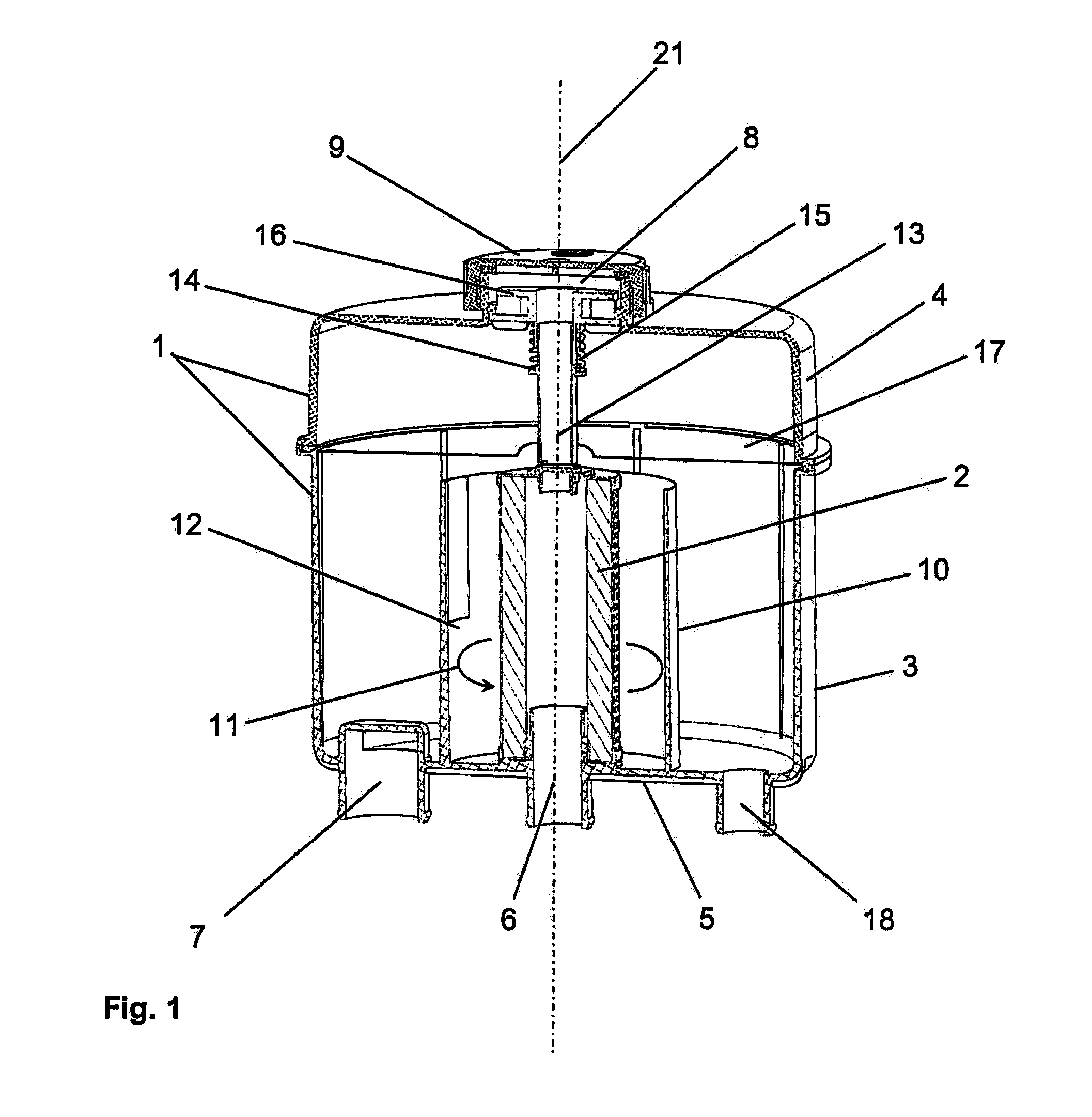
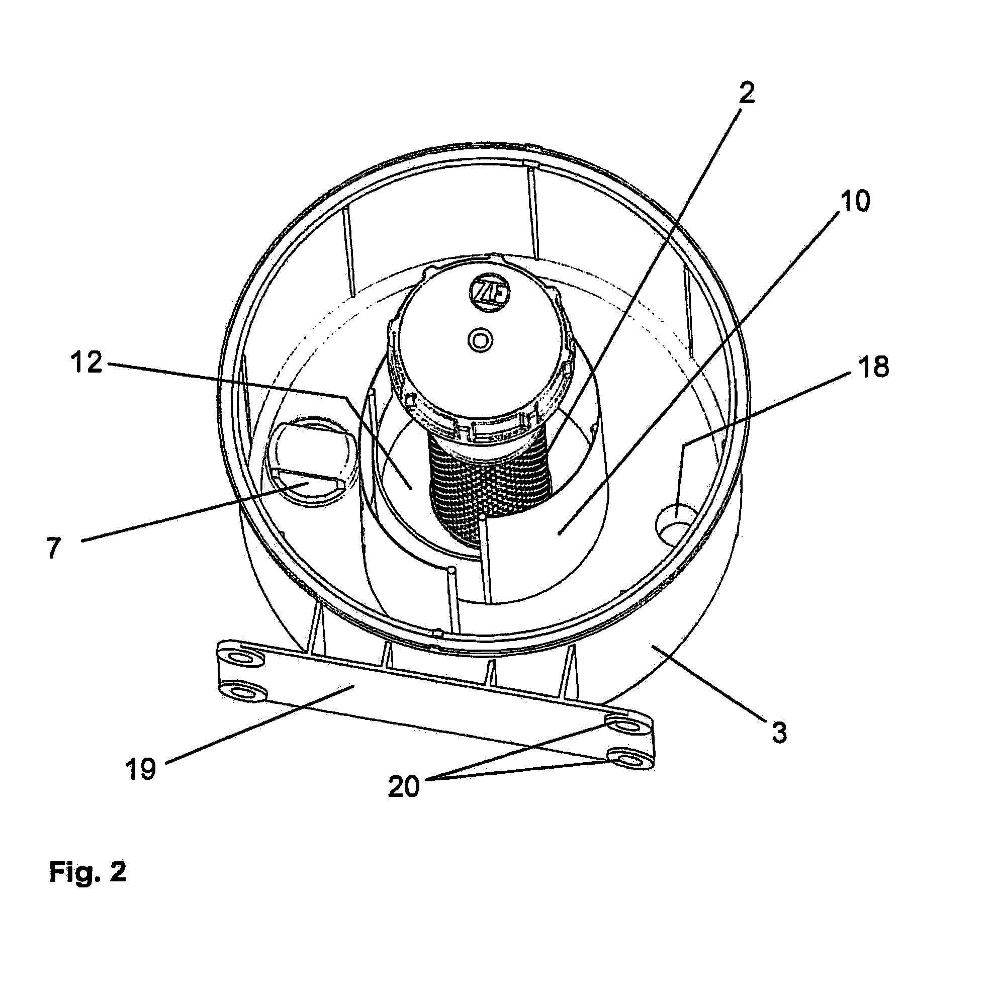
[0010]According to a preferred embodiment of the invention, the guide element is, or the guide elements are disposed around the oil filter. The guide element produces, or the guide elements produce a hollow-cylindrical space surrounding the preferably cylindrical oil filter. The inside walls of this hollow-cylindrical space form the circular guidance track for the oil, which in this case opens in the direction of the at least one oil outlet fitting. This embodiment is advantageously refined in that the circular guidance track is led around the oil filter in a spiral-shaped path in more than one full circulation. In this way, a long guiding track is produced and, with respect to separating the air, advantageous strong turbulence of the oil is achieved.
[0011]In a particularly advantageous embodiment of the oil reservoir according to the invention, the oil filter is equipped with a filter protection valve. This filter protection valve protects the oil filter from destruction by possibly occurring pressure peaks of the oil which enters the oil reservoir from the oil circuit by way of the oil inlet fitting and is supplied to the oil filter. For this purpose, when such pressure peaks occur, the filter protection valve opens a bypass by way of which part of the oil enters the guidance track without passing the oil filter and, by way of the guiding track, enters the oil outlet fitting or fittings. In order to protect the oil filter from destruction, it is acceptable that in rare cases when isolated pressure peaks occur a small part of the filter enters the circuit again without being filtered.
[0012]In keeping with a practical embodiment comprising a cylindrical reservoir housing, the oil inlet fitting and the at least one oil outlet fitting are configured on the reservoir bottom of the oil reservoir. The oil inlet fitting disposed in the center of the reservoir bottom opens directly into the oil filter, which is designed as a hollow cylinder, projects vertically upward from the inside of the reservoir bottom, and is closed at the top thereof. The oil outlet fitting is, or the oil outlet fittings are disposed laterally next to the oil filter and outside of the hollow-cylindrical space which surrounds the same and is formed by at least one guide element attached to the reservoir bottom. This embodiment can be further refined in that a baffle plate is disposed in the reservoir housing above the hollow-cylindrical space. This baffle plate prevents the oil, which has been forced to perform a rotational movement, from moving upward in the outer reservoir regions and a funnel-shaped vortex from forming in the oil filter, which would reduce the oil volume passing the filter. The lower housing part and the housing cover are preferably connected to each other by a welded joint, by means of which also the baffle plate extending horizontally between the lower housing part and the housing cover is attached to the reservoir housing.

Problems solved by technology

According to the prior art, such oil reservoirs are frequently not equipped with an oil filter.
Due to the special design, the oil filter is disposed completely beneath the oil level independently of the fill level otherwise present in the oil reservoir, so that the oil cannot pick up any air during filtration, which can impair the functionality of the cooling system and, as a result, may cause units in the motor vehicle to fail.
With respect to the necessary encapsulation of the oil filter inside the oil reservoir, however, the solution is comparatively complex.

Method used


Image

  • Oil reservoir comprising an oil filter
  • Oil reservoir comprising an oil filter
  • Oil reservoir comprising an oil filter

Examples


Embodiment Construction

[0018]FIG. 1 shows a possible embodiment of the oil reservoir according to the invention. The illustration is a spatial representation of the oil reservoir in an axial section, which is to say a representation having a section that is guided longitudinally through the reservoir or parallel to the longitudinal axis 21.

[0019]The oil reservoir substantially comprises a reservoir housing 1 and the oil filter 2 disposed therein, wherein the reservoir housing 1 is formed by a lower housing part 3 and a housing cover 4, which is connected to the lower housing part 3 by a welded joint. On the bottom 5 of the lower housing part, the reservoir 3 comprises fittings 6, 7, 18, these being an oil inlet fitting 6, an oil outlet fitting 7, and an additional inlet fitting 18 for leakage oil. The oil reservoir is connected to a hydraulic system, which is not shown in the figure, by way of the oil inlet fitting 6 and the oil outlet fitting 7, and thereby is part of an oil circuit. The hydraulic fluid ...


PUM


Abstract

An oil reservoir having an oil inlet fitting and at least one oil outlet fitting for connecting to a hydraulic system. The reservoir comprising a housing having a lower housing part and a reservoir cover which is connected to the lower housing part and includes an integrated oil filter. An oil filler neck, which can be closed by a cap, is configured on the housing cover. The reservoir housing is equipped with at least one guide element which is attached to at least one inside wall of the reservoir housing and forms a circular guidance track for the oil. This guidance track forces the oil flow in a circular manner, after entering the reservoir and passing through the oil filter but before exiting the oil reservoir, such that any air which may be present is separated from the oil and can exit the oil reservoir via an air outlet.

Description

[0001]This application is a National Stage completion of PCT / DE2008 / 050032 filed Nov. 13, 2008, which claims priority from German patent application serial no. 10 2007 054 901.8 filed Nov. 15, 2007.FIELD OF THE INVENTION[0002]The invention relates to an oil reservoir for a hydraulic system, comprising a reservoir housing and an oil filter integrated in the reservoir housing, wherein the reservoir housing is preferably made of plastic.BACKGROUND OF THE INVENTION[0003]Oil reservoirs are used, for example, in motor vehicle technology for storing the oil of a hydrostatic fan system circulated in a circuit through the reservoir for cooling the engine. According to the prior art, such oil reservoirs are frequently not equipped with an oil filter. However, since abraded particles or possible impurities must be filtered out of the oil in order to protect the components of the hydraulic system, an appropriate oil filter must be disposed in a different location of the system when using an oil...

Claims


Application Information

Patent Timeline
IPC IPC(8): B01D27/08B01D35/147
CPCB01D29/117B01D36/001B01D29/92
Inventor RENNER, UWEKARLSTEDT, ROLFLIPP, CHRISTOPH
Owner ROBERT BOSCH GMBH
Learn More