Air pressure buffer

a buffer and air technology, applied in the field of buffers, can solve problems such as inaccurate positioning or unsecured positioning, and achieve the effect of steady buffering effect and enhanced damping capability

Inactive Publication Date: 2012-04-19
HUA FENG MACHINERY
View PDF10 Cites 13 Cited by
  • Summary
  • Abstract
  • Description
  • Claims
  • Application Information

AI Technical Summary

Benefits of technology

[0003]The primary object of the present invention is to overcome the aforesaid shortcomings by providing an air pressure buffer to prevent buffer delay when external force is applied, enhance damping capability and generate steady buffering effect.
[0005]Compared with the conventional techniques, the structure of the invention set forth above provides many benefits, notably: 1. the air pressure buffer of the invention prevents buffer delay when applied by external forces; 2. the air pressure buffer of the invention enhances buffer damping capability and generates secured and steady buffering effect.

Problems solved by technology

As a result, buffer delay frequently takes place when the air cylinder is subject to external forces, and unstable pause conditions could occur during the cylinder shaft is undertaken buffering, thus the prior art provides limited buffering effect and could result in unsecured or inaccurate positioning.

Method used


Image

  • Air pressure buffer
  • Air pressure buffer
  • Air pressure buffer

Examples


first embodiment

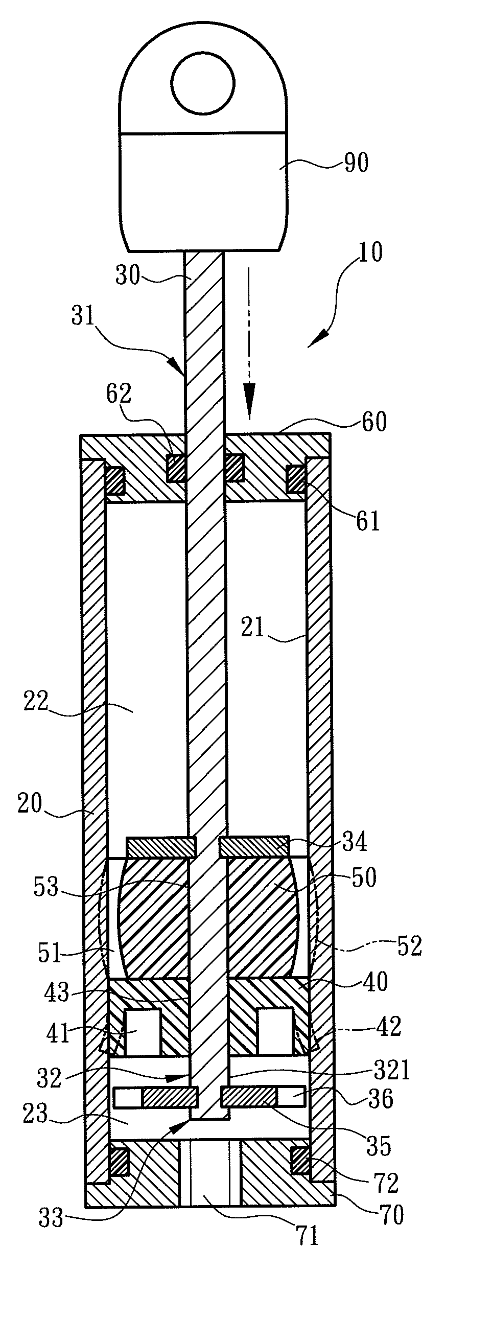
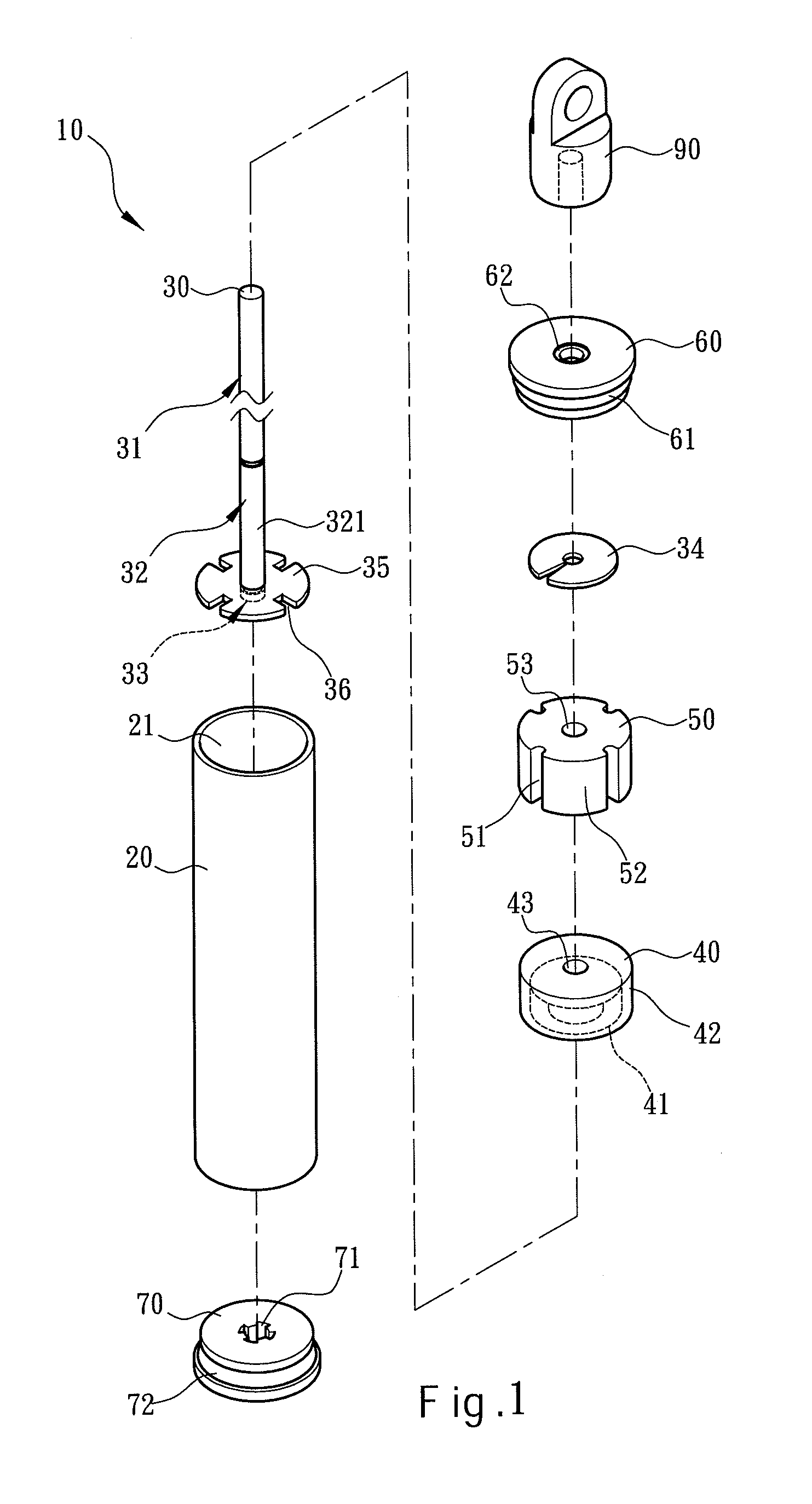
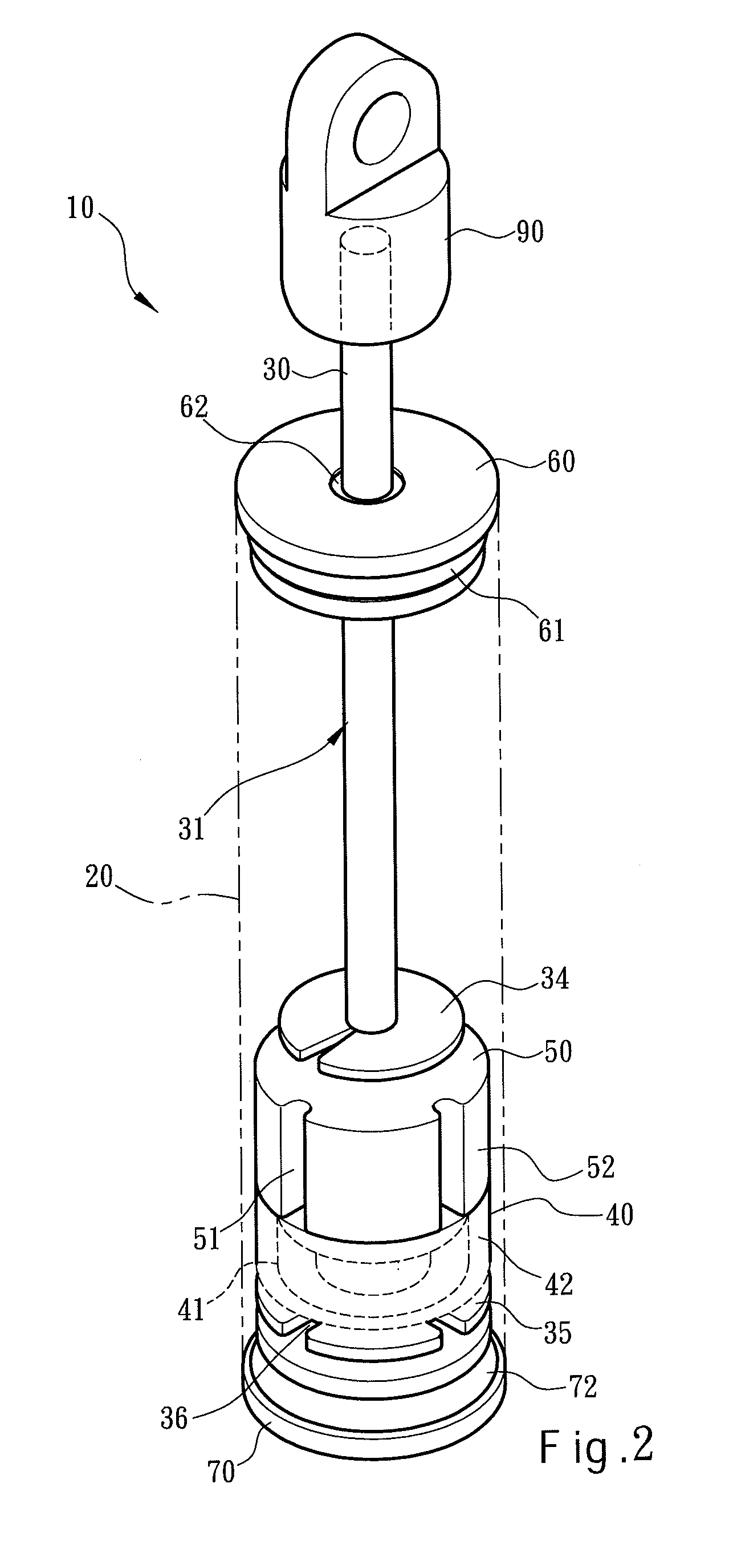
[0022]Please refer to FIGS. 1, 2, 3A through 3C for the invention. The air pressure buffer 10 according to the invention includes a hollow tube 20, a first cap 60 located at one end of the tube 20 that has a flexible first seal ring 61 made of rubber to tightly connect with the tube 20, and a shaft 30 running through the tube 20 and including a first section 31, a second section 32 and a third section 33. The first section 31 is extended outside the tube 20. The first cap 60 has a flexible second seal ring 62 made of rubber to tightly connect with the first section 31. The first section 31 has a distal end extended outside the tube 20 to fasten to a connector 90. The tube 20 holds a flexible valve 40 inside which surrounds the second section 32 in an annular manner. The valve 40 has an outer diameter the same as the inner diameter of the tube 20 and an outer surface 42 in contact with an inner wall 21 of the tube 20 in a sliding manner. The valve 40 has an inner diameter the same as...

second embodiment

[0026]Refer to FIGS. 8A through 8C for a variation of the second embodiment by adding a compression spring in the closed space 22. A compression spring 80 is installed in the closed space 22 between the first cap 60 and first retaining member 34. When the shaft 30 is moved downwards by external thrust as shown in FIG. 8A, the pressure of the compression spring 80 is greater than that of the open space 23, hence the downward thrust has to overcome the pressure of the compression spring 80 to make the valve 40 and compression member 50 to return to their original shapes quickly as shown in FIG. 8B with the shaft 30 being moved downwards. On the other hand, also referring to FIG. 8B, when the shaft 30 is moved upwards by an inverse pulling force, the outer surface 42 of the valve 40 is expanded outwards to squeeze the inner wall 21 of the tube 20 to form a tighter coupling, and simultaneously compresses the compression member 50 to generate deformation outwards to squeeze the inner wal...

fifth embodiment

[0029]Please refer to FIGS. 14A and 14B for the invention in continuous moving conditions. It is substantially the same as the one shown in FIGS. 7A and 7B, but it differs by integrating the first retaining member 34 and the first section 31 together, and also integrating the second retaining member 35 and third section 33 together without installing the second cap 70.


PUM


Abstract

An air pressure buffer includes a hollow tube, a first cap at one end of the tube, a shaft including a first section, a second section and a third section with the first section and / or third section extended outside the tube, a flexible valve which has an annular recess at one side to form an open space with the tube and second section extended to the third section and another side facing the first cap to form a closed space with the tube, the first cap and the second section extended to the first section, and a flexible compression member which has at least one axial ventilation groove on the outer surface thereof. The structure thus formed does not have buffer delay while being applied by an external force and provides enhanced buffer damping capability and steady and secure buffering effect.

Description

FIELD OF THE INVENTION[0001]The present invention relates to a buffer for household hardware and particularly to an air pressure buffer that uses air pressure for damping.BACKGROUND OF THE INVENTION[0002]In early days, pliable rubber pads or elastic springs and reeds are generally adopted to be buffers to avert direct impact of objects to reduce shock and noise. However, as used in houses to cushion impact, such as closing doors against door frames or pushing drawers into cabinets, a buffer usually is employed to reduce closing speed and impact. Applicant has disclosed an air pressure hinge in P.R.C. patent No. CN2685495Y. Refer to FIGS. 3 and 4 in this prior art, it includes an air cylinder and a telescopic cylinder axle with one end exposed outside that has an axle hole formed thereon and a hinge portion run through by a first pivot to be hinged on a butting member. The cylinder shaft has another end coupled with a regulation valve made of plastics or rubber. The regulation valve ...

Claims


Application Information

Patent Timeline
Patent Type & Authority Applications(United States)
IPC IPC(8): F16F11/00F16F13/00
CPCF16F9/516F16F9/0218
Inventor YANG, CHING-CHUAN
Owner HUA FENG MACHINERY
Why Eureka
Try Eureka