Rotary eddy current testing probe device

a technology of rotary eddy current and testing probe, which is applied in the direction of measuring devices, magnetic measurements, instruments, etc., can solve the problems of insufficient detection capacity of conventional rotary eddy current probe devices, and achieve the reduction of variations in flaw signals caused by the flaw direction, test time can be shortened, and the effect of reducing the variation of flaw signals

Active Publication Date: 2012-04-19
NIPPON STEEL CORP
View PDF1 Cites 6 Cited by
  • Summary
  • Abstract
  • Description
  • Claims
  • Application Information

AI Technical Summary

Benefits of technology

[0017]According to the present invention, the rotary eddy current testing probe device can detect flaws in all directions without omission regardless of the direction of flaw on the object being inspected. The rotary eddy current testing probe device of the present invention can detect flaws in a wider range in one movement (i.e. scan) of the rotary eddy current probe device: the testing range of the conventional rotary eddy current testing probe device is about 2 mm, whereas the testing range of the rotary eddy current testing probe device of the present invention is 10 mm or wider. Therefore, the rotary eddy current testing probe device of the present invention can detect flaws in a wide range by one flaw detection, so that the testing time can be shortene

Problems solved by technology

The conventional rotary eddy current probe device has difficulty in detecting a flaw intersecting at right angles with the movement direction of the rotary eddy current probe device as desc

Method used


Image

  • Rotary eddy current testing probe device
  • Rotary eddy current testing probe device
  • Rotary eddy current testing probe device

Examples


Embodiment Construction

[0028]A rotary eddy current probe device in accordance with an embodiment of the present invention will now be described with reference to FIGS. 1 to 3.

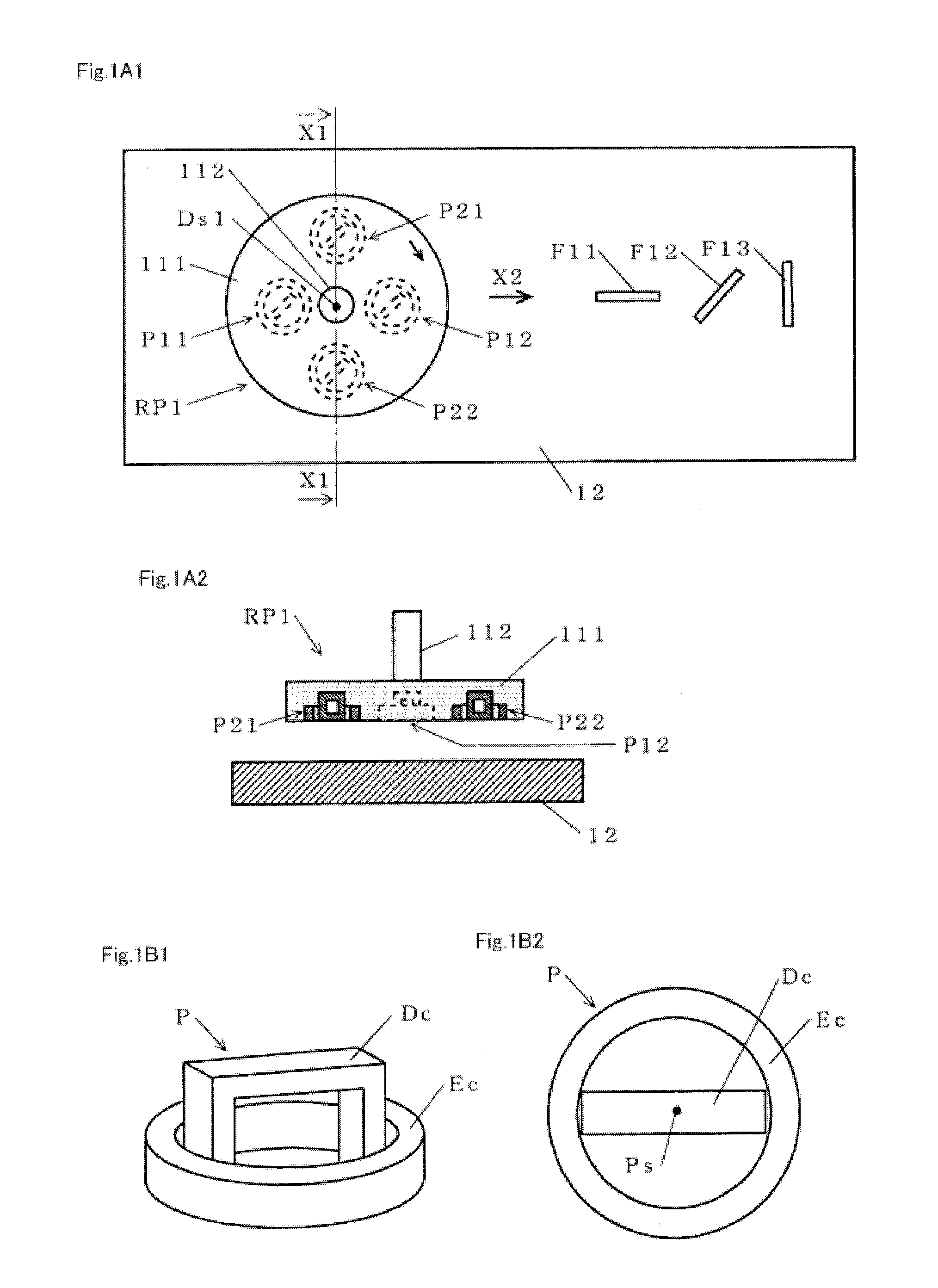
[0029]First, FIGS. 1A1, 1A2, 1B1 and 1B2 are explained.

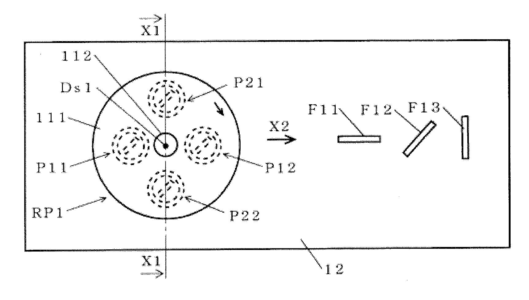
[0030]FIG. 1A1 is a plan view of the rotary eddy current probe device and an object being inspected, FIG. 1A2 is a sectional view taken along the line X1-X1 of FIG. 1A1, FIG. 1B1 is a perspective view of a Θ-shaped eddy current probe, and FIG. 1B2 is a plan view of the Θ-shaped eddy current probe.

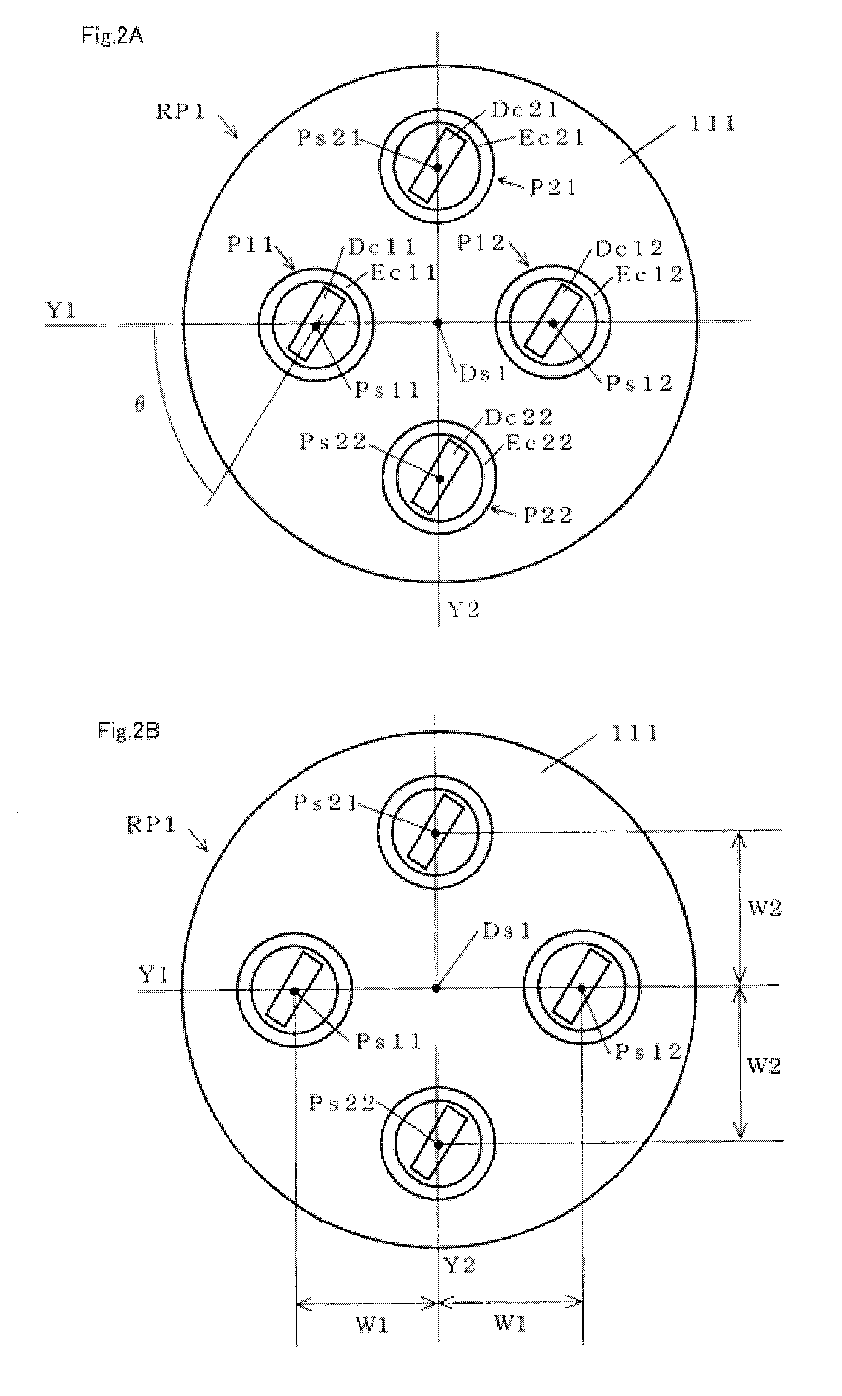
[0031]The rotary eddy current probe device RP1 has four Θ-shaped eddy current probes P11, P21, P12 and P22 (hereinafter, P is sometimes used as the general symbol for P11, P21, P12 and P22) and a rotating disc 111. The eddy current probes P11, P21, P12 and P22 are embedded in the rotating disc 111 by molding, and are arranged so as to face the inspection surface of the object being inspected 12 for which the presence of a flaw is inspected. The rotating disc 111 is rotated by the rotatio...


PUM


Abstract

A rotary eddy current flaw detection probe device has a plurality of Θ-shaped eddy current flaw detection probes attached in a rotating disc for detecting flaws in all directions regardless of the flaw direction. Four Θ-shaped eddy current testing probes P11 to P22 are arranged around the rotation center Ds1 of a rotating disc 111, and are embedded in the disc 111. The coil planes of detector coils Ds11 to Ds22 of the testing probes P11 to P22 are parallel with each other, and are perpendicular to the rotation plane of the rotating disc 111. The coil planes of the detector coils incline at an angle θ relative to a line Y passing through the centers Ps11 and Ps12 of the probes P11 and P12. The detector coils Dc11 and Dc12 are cumulatively connected to each other, and the detector coils Dc21 and Dc22 are differentially connected to each other.

Description

TECHNICAL FIELD[0001]The present invention relates to a rotary eddy current testing probe device for detecting flaws by rotating and moving a rotating disc (to scan) to which a plurality of eddy current testing probes are attached.BACKGROUND ART[0002]There has conventionally been proposed an rotary eddy current testing probe device for detecting flaws in all directions in an electric conductor such as a metal by rotating and moving a rotating disc to which a plurality of eddy current testing probes are attached (for example, refer to JP2007-248169A).[0003]In this description, an eddy current testing probe is referred to as an eddy current probe, and a device including a rotating disc to which a plurality of eddy current testing probes are attached is referred to as a rotary eddy current testing probe device. The rotary eddy current testing probe device is abbreviated to a rotary eddy current probe device as appropriate.[0004]A coil axis means an axis that is the center of spiral win...

Claims


Application Information

Patent Timeline
IPC IPC(8): G01N27/90
CPCG01N27/904G01N27/902
Inventor HIBINO, TAKASHIFUJIMOTO, TAKASHINAMEKATA, SHIGEKIKOMATSU, KEISUKENAKAO, YOSHIYUKITAKATA, MAKOTOSAKAMOTO, MAKOTO
Owner NIPPON STEEL CORP
Why Eureka
Try Eureka