Tire inspection apparatus

a technology for inspection apparatus and tires, applied in vehicle tyre testing, instruments, roads, etc., can solve the problems of long transfer time, impediment to smooth inspection performance, waste of time, etc., and achieve the effect of easy image synthesis

Inactive Publication Date: 2012-04-19
BRIDGESTONE CORP
View PDF6 Cites 28 Cited by
  • Summary
  • Abstract
  • Description
  • Claims
  • Application Information

AI Technical Summary

Benefits of technology

[0060]According to the invention, the neighboring regions are shot by the image shooting means such as to have overlaps. Thus the sho

Problems solved by technology

For example, it is necessary to inspect the inner surface of a tire closely since the defects thereon cannot be visually checked after it is fitted on the wheel.
Thus result the waiting times C1 and C2, which can be a waste of time.
This causes a longer time for transfer of the shot images P1 to P3, which occasionally results in waiting for the transfer or the like.
This is also an impediment to smooth performance of inspection of the next tire T.
Further, an inspection by a single session of image shooting does not necessarily result in a successful image shooting of the tire i

Method used


Image

  • Tire inspection apparatus
  • Tire inspection apparatus
  • Tire inspection apparatus

Examples


first embodiment

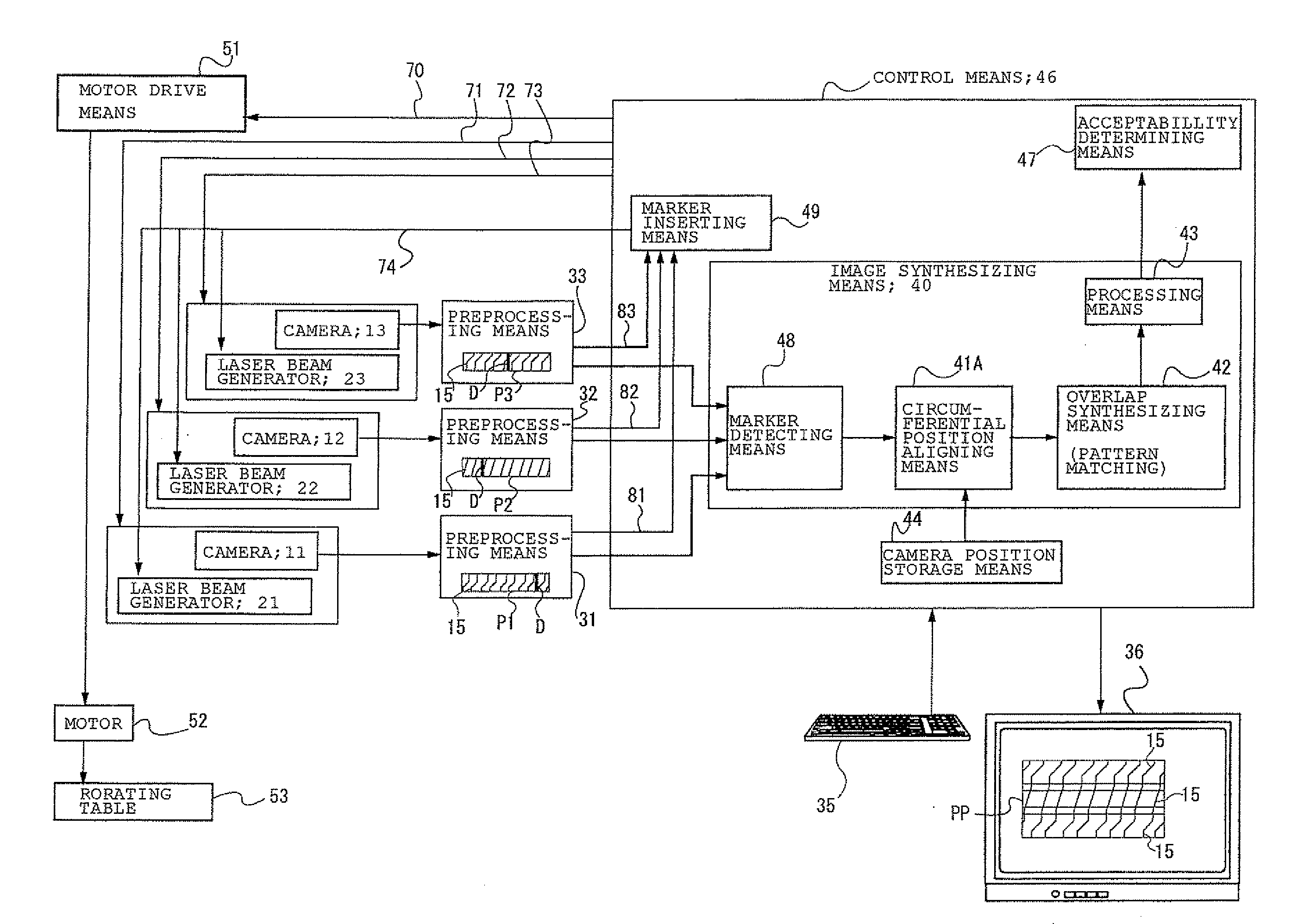
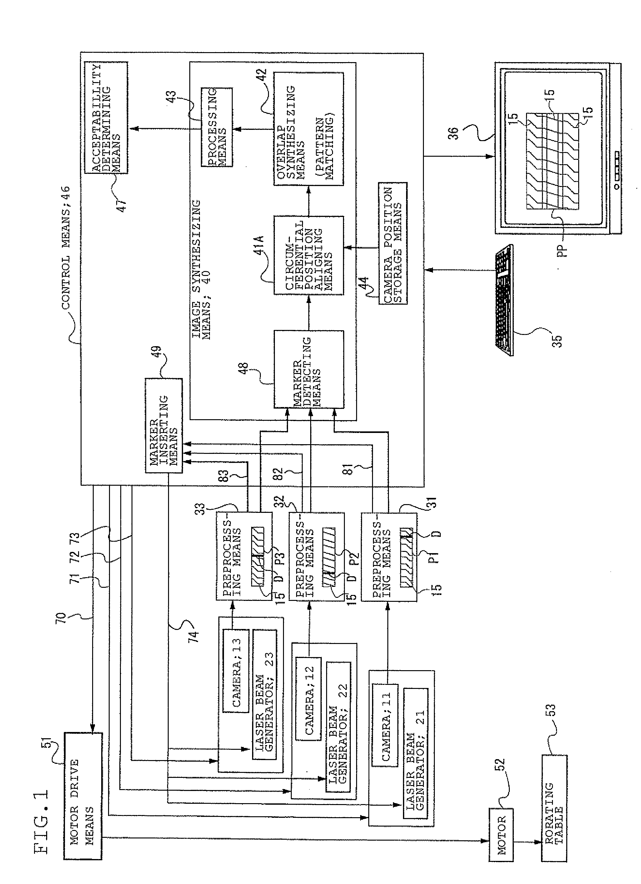
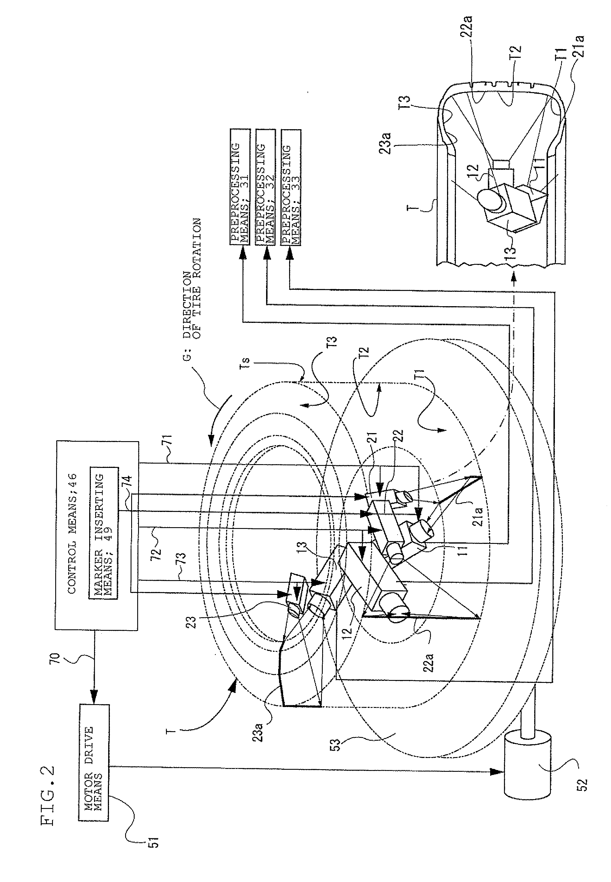
[0080]FIG. 1 is a block diagram showing a preferred embodiment in which a tire inspection apparatus according to the present invention is applied to the inspection of the tire inner surface Ts of the circumferential surfaces of a tire to be inspected. FIG. 2 is an enlarged illustration of an inspection apparatus which is represented in a block diagram in FIG. 1. Note that, in FIGS. 1 and 2, the identical reference numerals are given to the identical components found in FIG. 14.

[0081]As shown in FIGS. 1 and 2, a tire T, which is an object to be inspected, is placed on its side on a rotating table 53 in such a manner that the center of the tire T is aligned with the center axis of the rotating table 53. Driven by a motor 52, the rotating table 53 rotates in the direction of arrow G. In the center opening area of the tire T, a not-shown suspension member is installed vertically from above the tire T. And mounted to the end of the suspension member are laser beam generators 21 to 23, wh...

second embodiment

[0126]In the first embodiment, after the insertion of dark lines D as the markers by the marker inserting means 49, the numbers of shootings by the cameras 11 to 13 are reset, and the numbers of shootings thereby are counted again. However, the arrangement may be such that the rotation of the tire T is stopped at the insertion of the dark lines D.

[0127]More specifically, the marker inserting means 49 is connected to the laser beam generators 21 to 23 via a marker insertion line 74 and also to the motor drive means 51 via a temporary stop signal line. Thus, the arrangement is such that when the dark lines D are inserted by the laser beam generators 21 to 23, the rotation of the tire T is stopped temporarily for a time length equivalent to a single shooting.

[0128]In this case, the image shooting by the cameras 11 to 13 suffices if the number of shootings from the start of image shooting covers “number of shootings for full tire circle+one time of shooting”. Note that the counting of t...


PUM


Abstract

A inspection apparatus arranged with a plurality of cameras located at relatively displaced circumferential positions and set for the respective shooting positions different from each other in the axial direction of the tire. Thus the images of the inner circumferential surface of the tire are shot by the plurality of cameras as the tire is rotated circumferentially relative to the plurality of cameras. During this operation, markers are inserted at the same time in the images shot by all of the cameras. The images are synthesized using these markers as reference positions in aligning the shot images in accordance with the relative displacements of the cameras in the circumferential direction.

Description

TECHNICAL FIELD[0001]The present invention relates to an apparatus for inspecting the appearance of tires. In particular, the invention relates to a tire inspection apparatus for inspecting the inner surface or the outer surface of a tire.BACKGROUND ART[0002]The appearance inspection of a tire is important in checking for the presence of defects on the tire which has been cure-molded into a product. For example, it is necessary to inspect the inner surface of a tire closely since the defects thereon cannot be visually checked after it is fitted on the wheel.[0003]Conventionally, the tire inner surface Ts has been closely inspected for molding defects and the like, using a tire inspection apparatus as shown in FIG. 14. In carrying out the inspection, cameras 11 to 13 as the image shooting means and laser beam generators 21 to 23 as the illuminating means casting slit light 21a to 23a are disposed in the center opening space of a tire T rotating circumferentially, and the images of po...

Claims


Application Information

Patent Timeline
IPC IPC(8): B60C23/02
CPCG01B11/245G01B11/2513G01N21/954G01N21/952G01M17/027
Inventor FUJISAWA, YOSHITAKA
Owner BRIDGESTONE CORP
Why Eureka
Try Eureka