Backlight unit and display apparatus employing the same

a backlight unit and display apparatus technology, applied in non-linear optics, instruments, optics, etc., can solve the problems of reducing the resolution of the backlight pattern and difficulty in accurate control of the backlight unit, so as to achieve accurate control of the light pattern and uniform illumination

Inactive Publication Date: 2012-04-19
SAMSUNG ELECTRONICS CO LTD
View PDF2 Cites 21 Cited by
  • Summary
  • Abstract
  • Description
  • Claims
  • Application Information

AI Technical Summary

Benefits of technology

[0009]Exemplary embodiments provide a reconfigurable backlight unit capable of accurately controlling a light pattern and uniform illumination, and a display apparatus employing the same.
[0019]One of the transparent electrode and the reflective electrode may be in the form of horizontally aligned stripes so as to be used as an address electrode, and the other of the transparent electrode and the reflective electrode may be used as a common electrode, thereby generating backlight scanning
[0020]One of the transparent electrode and the reflective electrode may be in the form of a 2D array so as to perform addressing individually or by using a matrix method, and the other of the transparent electrode and the reflective electrode may be used as a common electrode, thereby generating local dimming.

Problems solved by technology

However, since an area of an image panel of the liquid crystal display apparatus, which is illuminated by each LED, overlaps an area corresponding to another LED, accurate control of the backlight unit is not easy.
Due to high cost, the number of LEDs in a backlight unit is not generally large and thus each LED is mounted together with an optical lens having a shape for spreading light emitted from the LED to a wide area on the diffuser.
As a result, a pattern generated by the backlight is reduced in resolution and thus is blurred.

Method used


Image

  • Backlight unit and display apparatus employing the same
  • Backlight unit and display apparatus employing the same
  • Backlight unit and display apparatus employing the same

Examples


Embodiment Construction

[0032]A reconfigurable backlight unit according to an exemplary embodiment includes a combination of liquid crystal panel technology and light guide plate technology. Hereinafter, a backlight unit and a display apparatus employing the same according to an exemplary embodiment will be described in detail with reference to the attached drawings. In the drawings, like reference numerals denote like elements and the sizes or thicknesses of elements may be exaggerated for clarity of explanation. Also, various changes in form and details may be made in the following exemplary embodiments.

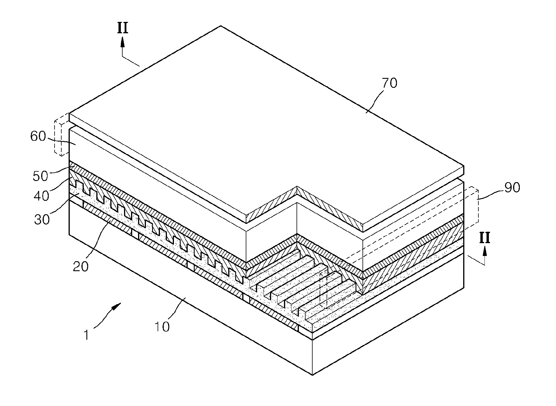
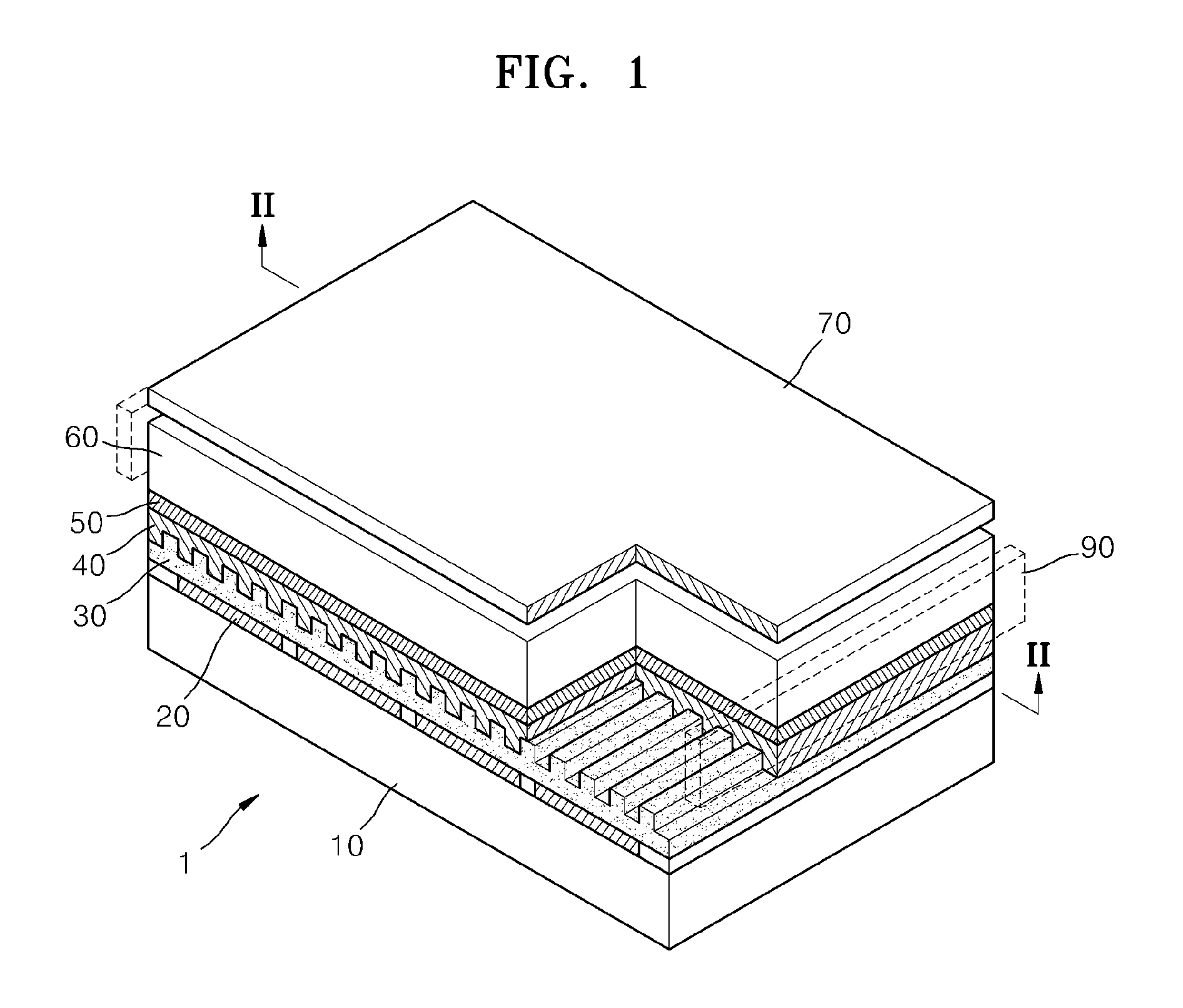
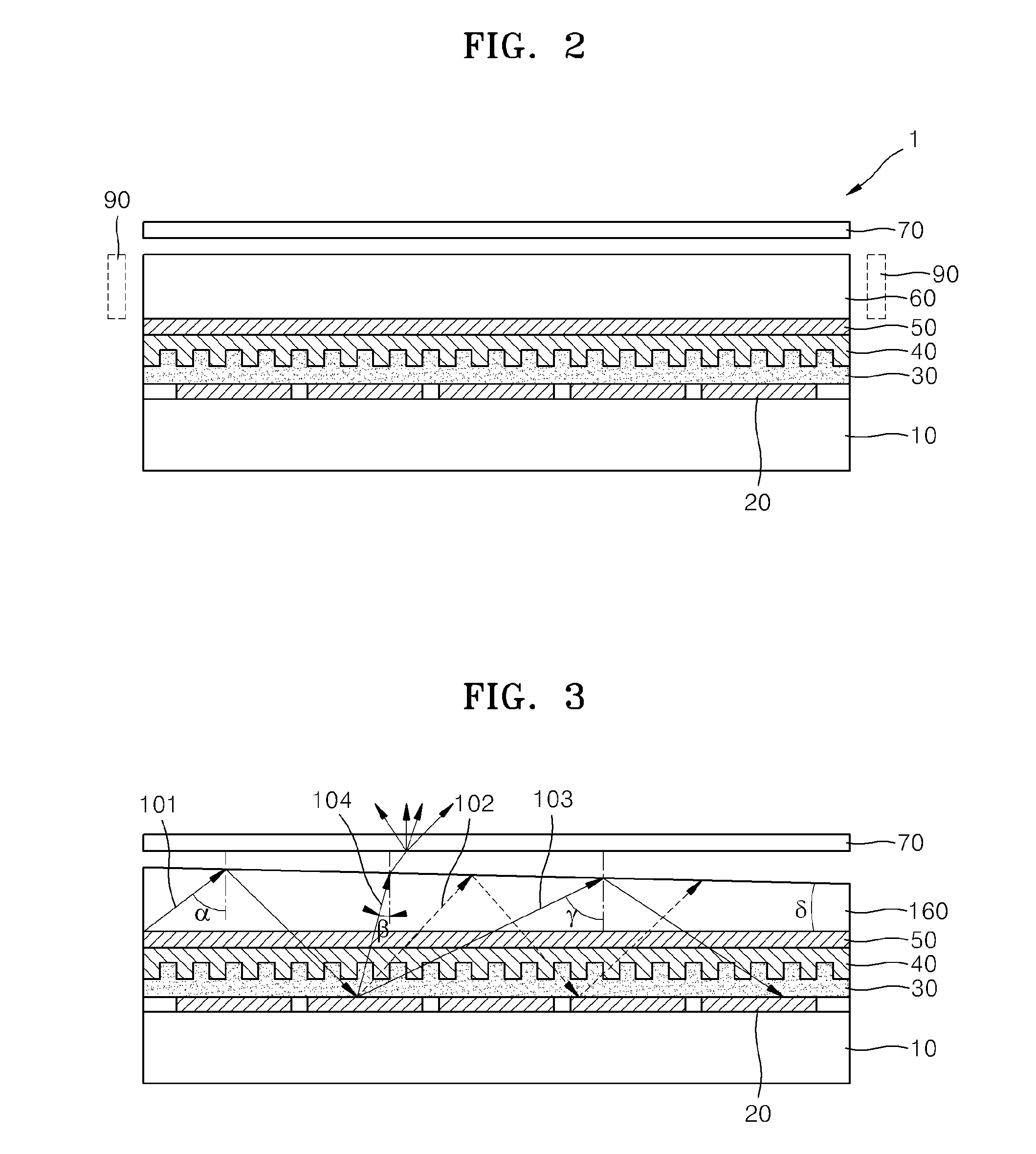
[0033]FIG. 1 is a perspective view of a portion of a backlight unit according to an exemplary embodiment. FIG. 2 is a cross-sectional view cut along a line II-II of FIG. 1. FIG. 3 is a cross-sectional view of an example when a wedge-type substrate substitutes a first substrate illustrated in FIGS. 1 and 2.

[0034]Referring to FIGS. 1 and 2, the backlight unit includes a light source 90 and a liquid crystal ...


PUM

PropertyMeasurementUnit
transparentaaaaaaaaaa
refractive indexaaaaaaaaaa
refractive indicesaaaaaaaaaa

Abstract

A backlight unit including a light source; and a liquid crystal panel. The liquid crystal panel includes a first substrate which guides light incident from the light source disposed at at least one side of the first substrate; a transparent electrode disposed on a surface of the first substrate; a second substrate; a reflective electrode disposed on a surface of the second substrate facing the transparent electrode; a liquid crystal layer disposed between the transparent electrode and the reflective electrodes; and a transparent film disposed between the transparent electrode and the reflective electrodes, the transparent film including a surface contacting the liquid crystal layer and patterned with grooves or ribs , and having a refractive index corresponding to at least one of an ordinary refractive index and an extraordinary refractive index of liquid crystals of the liquid crystal layer.

Description

CROSS-REFERENCE TO RELATED PATENT APPLICATION[0001]This application claims priority from Korean Patent Application No. 10-2010-0099841, filed on Oct. 13, 2010 in the Korean Intellectual Property Office, the disclosure of which is incorporated herein in its entirety by reference.BACKGROUND[0002]1. Field[0003]Apparatuses consistent with exemplary embodiments generally relate to a backlight unit and a display apparatus employing the same.[0004]2. Description of the Related Art[0005]A general reconfigurable backlight unit used to produce local dimming includes a two-dimensional (2D) array of light-emitting diodes (LEDs), and a diffuse sheet. The general reconfigurable backlight unit may be controlled by individually driving the LEDs. A backlight unit of a liquid crystal display apparatus for performing local dimming should generate an accurately controllable light pattern for backlighting a liquid crystal panel when a high-contrast image is displayed, and should provide uniform illumina...

Claims


Application Information

Patent Timeline
Patent Type & Authority Applications(United States)
IPC IPC(8): G02F1/1335
CPCG02F1/133504G02F2001/133616G02F1/133615G02F1/133611G02F1/133616
Inventor SHESTAK, SERGEYCHA, KYUNG-HOON
Owner SAMSUNG ELECTRONICS CO LTD
Why Eureka
Try Eureka