System and Methods for Intrapulse Multi-energy and Adaptive Multi-energy X-ray Cargo Inspection

a multi-energy, adaptive technology, applied in the direction of material analysis, material analysis using wave/particle radiation, instruments, etc., can solve the problems of ineffective tandem-detector configuration, extended dual energy methods, and ineffective inspection of tandem-detector configurations

Active Publication Date: 2012-04-19
AMERICAN SCI & ENG INC
View PDF2 Cites 21 Cited by
  • Summary
  • Abstract
  • Description
  • Claims
  • Application Information

AI Technical Summary

Problems solved by technology

More recently, the dual energy methods have been extended to high-energy inspection systems for cargo containers, where they are less effective due to the weaker Z-dependence of the dominant interaction.
However, tandem-detector configurations tend to be ineffectual for inspection at energies above ˜1 MeV, because the beam is typically so hardened by traversal of the intervening cargo that there is little differential detection between the detector elements.
Moreover, the signals from each element of a tandem detector are also typically cross-contaminated by Compton scattered photons: the forward low-energy detector signal is contaminated by backscattered photons, whereas the signal produced in the rearward high-energy element is contaminated by forward scattered photons.
The use of dual energy beams, however, gives rise to ambiguity in determining the atomic number of a sample.
A further disadvantage of currently practiced multiple-energy techniques involves the use of linear accelerators (linacs) to generate X-ray pulses in the MeV range used for cargo inspection.
This variation requires an equivalent dynamic range for the detection system, a daunting challenge to effective inspection techniques.

Method used


Image

  • System and Methods for Intrapulse Multi-energy and Adaptive Multi-energy X-ray Cargo Inspection
  • System and Methods for Intrapulse Multi-energy and Adaptive Multi-energy X-ray Cargo Inspection
  • System and Methods for Intrapulse Multi-energy and Adaptive Multi-energy X-ray Cargo Inspection

Examples


Embodiment Construction

[0017]In accordance with embodiments of the invention, methods and apparatus are provided for inspecting an object with x-rays. In one embodiment of the invention, a method for x-ray inspection of an object has steps of:

[0018]a. generating a temporal sequence of pulses of penetrating radiation, each pulse characterized by an onset and by a spectral content that evolves with time subsequent to the onset;

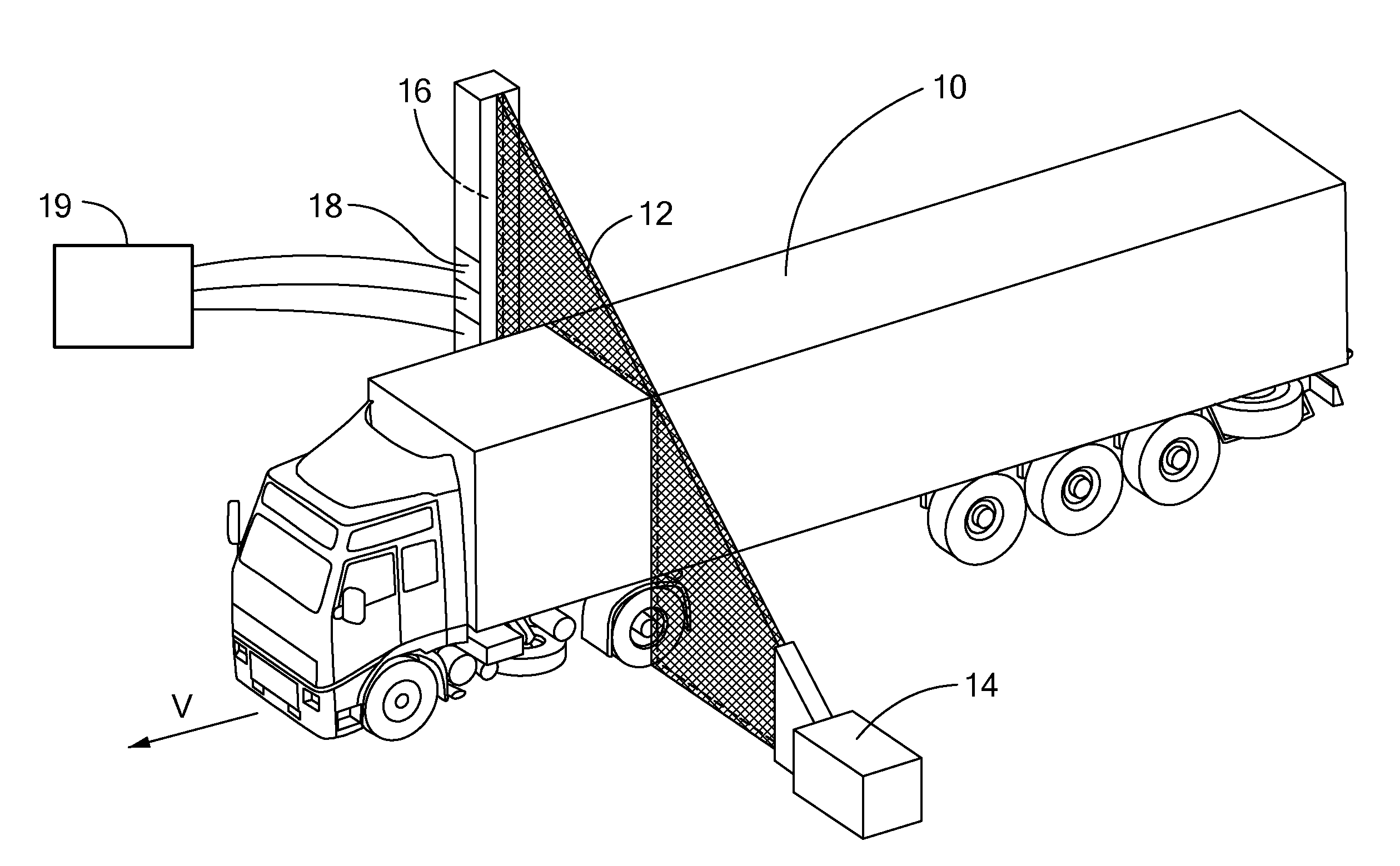
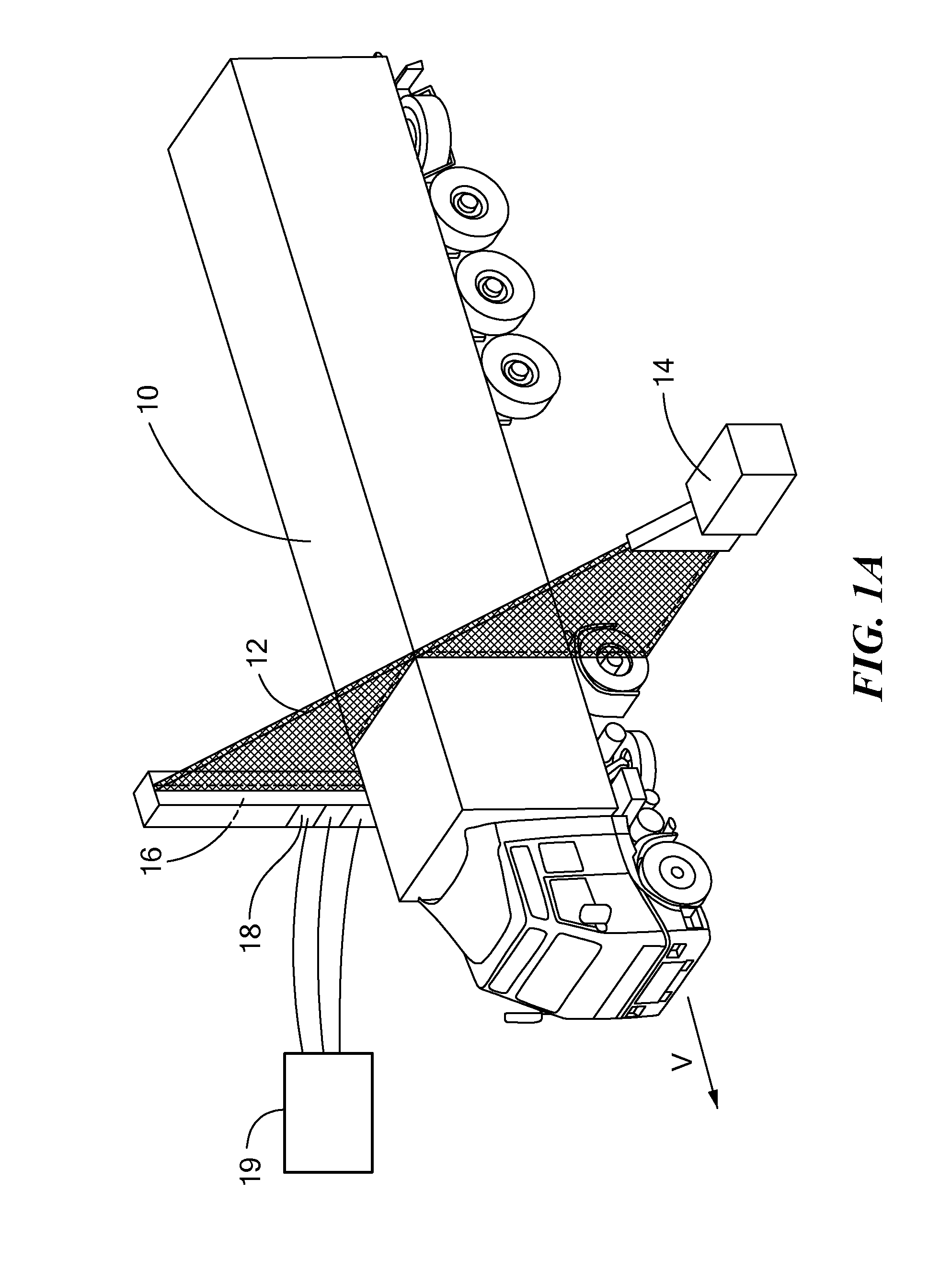
[0019]b. forming the pulses of penetrating radiation into a beam scanned across the object;

[0020]c. detecting penetrating radiation from the beam that has traversed the object and generating a detector signal; and

[0021]d. processing the detector signal to derive at least one material characteristic of the object on a basis of temporal evolution of the detector signal of at least one pulse of the sequence of pulses.

[0022]In accordance with further embodiments, the step of detecting penetrating radiation may include distinguishing signal acquired during distinct time intervals of each p...


PUM

PropertyMeasurementUnit
end-point energyaaaaaaaaaa
thicknessaaaaaaaaaa
energyaaaaaaaaaa

Abstract

Methods and systems for x-ray inspection of an object using pulses whose spectral composition varies during the course of each pulse. A temporal sequence of pulses of penetrating radiation is generated, each pulse characterized by an onset and by a spectral content that evolves with time subsequent to the onset. The pulses are formed into a beam that is scanned across the object. The penetrating radiation from the beam that has traversed the object is detected, generating a detector signal. The detector signal is processed to derive at least one material characteristic of the object, such as effective atomic number, on the basis of temporal evolution of the detector signal during the course each pulse of the sequence of pulses. The detector signal is separately acquired for multiple time intervals relative to the pulse onset, and processed to obtain values corresponding to multiple-energy analysis of the transmitted radiation. The time intervals may be predetermined, or else adapted based on features of the detected signal.

Description

[0001]The present application claims priority from U.S. Provisional Patent Application Ser. No. 61 / 394,052, filed Oct. 18, 2010, and incorporated herein by reference.TECHNICAL FIELD[0002]The present invention relates to methods and apparatus for cargo inspection with penetrating radiation, and, more particularly, to inspection systems employing pulsed X-ray sources with non-stationary spectrum and intensity, providing enhanced material discrimination.BACKGROUND ART[0003]X-ray security inspection systems for the inspection of cargo and shipping containers typically use transmission radiographic techniques. FIG. 1A depicts a cargo inspection system employing such a technique. A fan-shaped beam 12 of penetrating radiation, emitted by a source 14, is detected by elements of a detector array 16 distal to a target object, here truck 10, is used to produce images of the target object. The thickness of material to be penetrated by the X-rays may exceed 300 mm of steel equivalent in some cas...

Claims


Application Information

Patent Timeline
Patent Type & Authority Applications(United States)
IPC IPC(8): G01N23/04
CPCG01V5/0041
Inventor ARODZERO, ANATOLIROMMEL, MARTINSAVERSKIY, ALEKSANDRSUD, RAJEN
Owner AMERICAN SCI & ENG INC
Why Eureka
Try Eureka