
Arc resistant electrical enclosure

a technology of electrical enclosure and arc resistance, which is applied in the direction of electrical apparatus casings/cabinets/drawers, gaseous cathodes, substation/switching arrangement casings, etc. it can solve the problems of expansion of hot gas volume, increased sudden pressure, and localized overheating, so as to enhance the structural support of the enclosure and add structural strength

Active Publication Date: 2012-04-26
ROCKWELL AUTOMATION TECH
View PDF28 Cites 41 Cited by
  • Summary
  • Abstract
  • Description
  • Claims
  • Application Information

AI Technical Summary

Benefits of technology

[0005]The arc resistant enclosures described herein include arc resistant features. In general, the arc resistant features include features designed to add structural strength for arc containment, to inhibit arc propagation, and/or to direct the release of pressure within and/or from the enclosure in order to provide arc resistant electrical enclosures that can withstand an internal arcing fault. For example, the enclosures may include a pressure relief device that allows gases to escape from a certain area of the enclosure. Further, the enclosures may include in

Problems solved by technology

A particular challenge in the design and operation of electrical components in enclosures relates to designing the enclosures to withstand the mechanical and thermal effects of an internal arcing fault (also called an arc, arc fault, arc flash, arcing flash, etc.).
For example, certain types of electrical faults can produce arcs that can heat and even vaporize neighboring components and cause sudden pressure increases and localized overheating.
Such faults can result in volumes of hot gas that expand and must be channeled and / or vented within or from the enclosure.
Further, the faults can produce high temperatures and pressure increases that cause mechanical and thermal stresses on the electrical enclosures.
Arcing faults can cause damage to equipment and facilities and increase costs due to lost production.

Method used


Image

  • Arc resistant electrical enclosure
  • Arc resistant electrical enclosure
  • Arc resistant electrical enclosure

Examples


Embodiment Construction

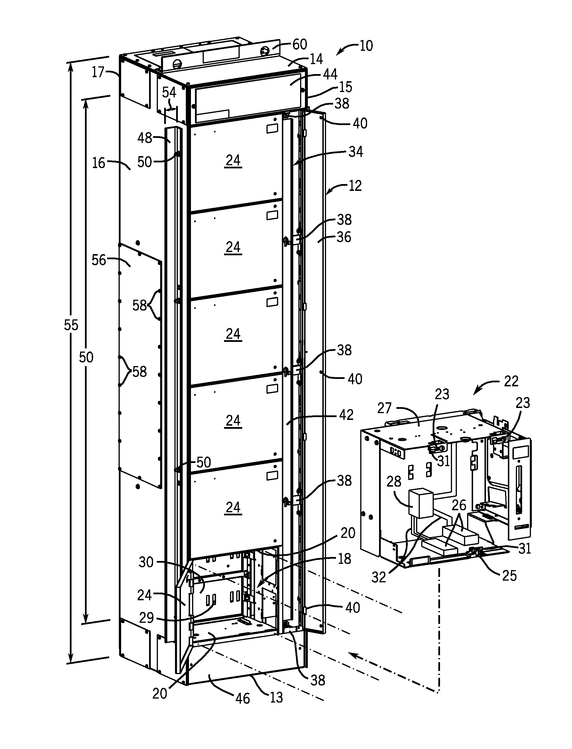
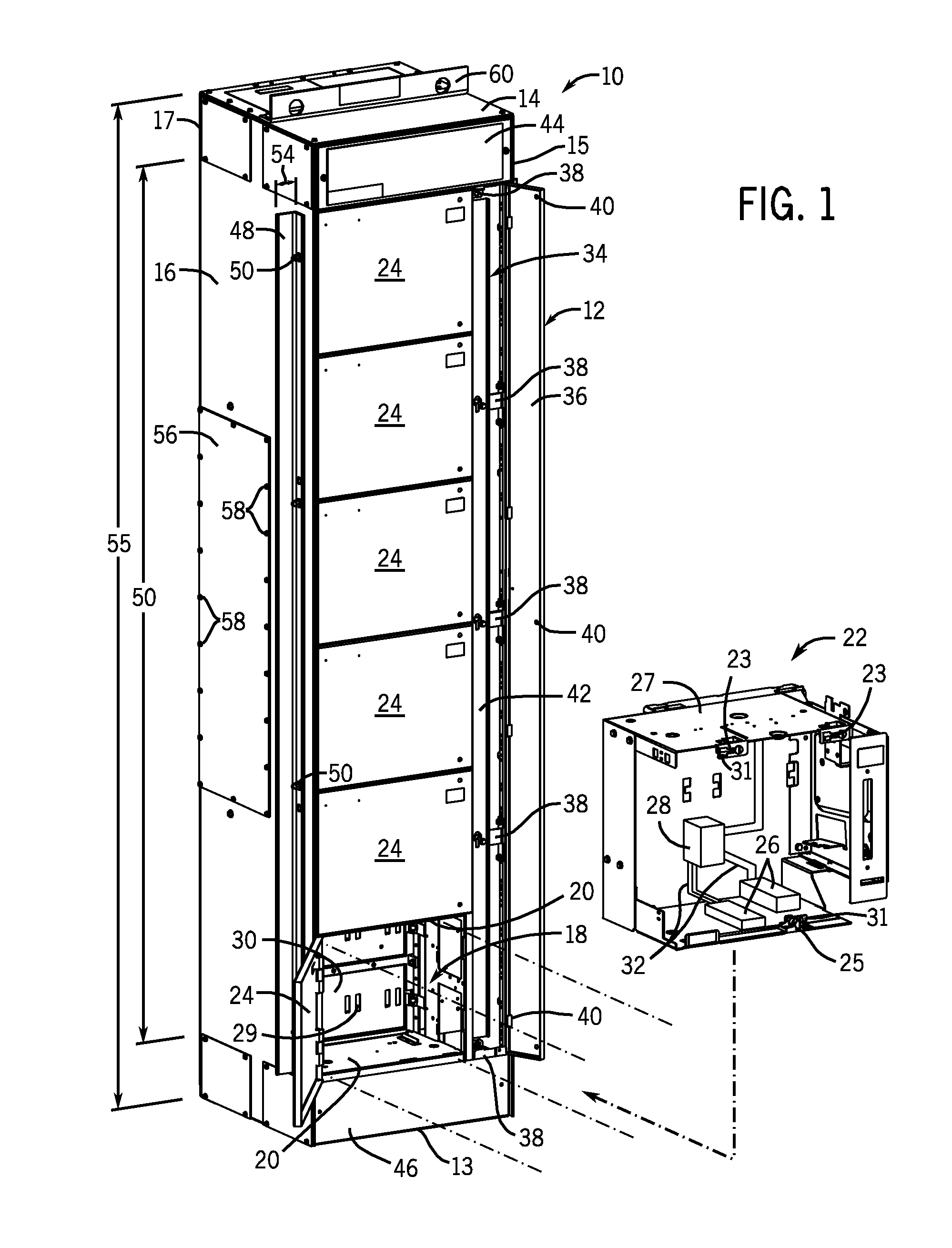
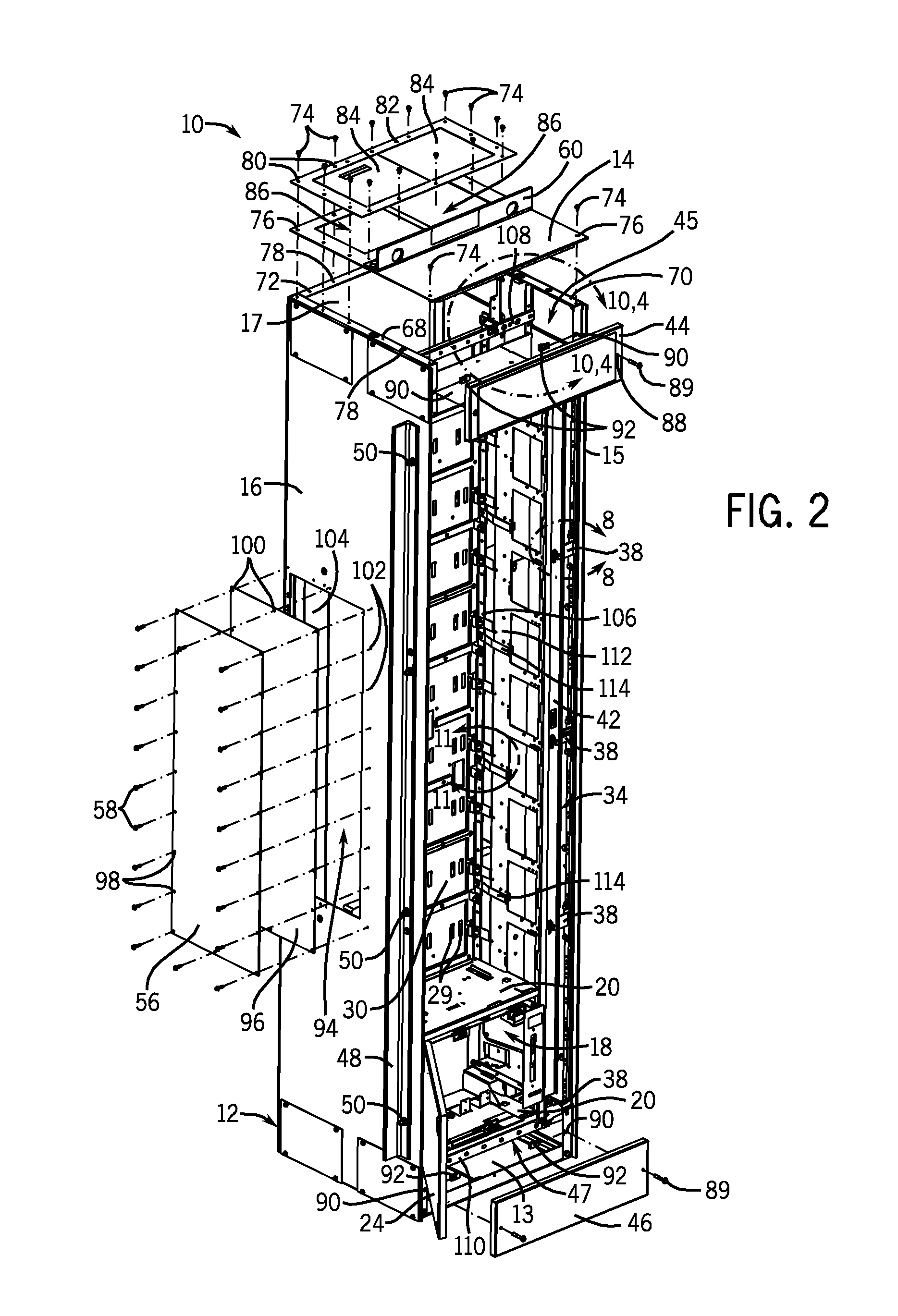
[0023]FIG. 1 depicts an embodiment of an arc resistant electrical enclosure 10. In general, the arc resistant electrical enclosures 10 are enclosures designed to withstand the mechanical and thermal effects of an internal arcing fault. The enclosures 10 include arc resistant features designed to add structural strength for arc containment, to inhibit arc propagation, and / or to direct the release of pressure within and / or from the enclosure. The arc resistant features may be designed to provide enclosures where in the event of an arc fault, the doors and covers remain closed, parts are not ejected from the enclosure, holes are not produced in the enclosure, indicators located in close proximity to the enclosure do not ignite, and / or grounding connections remain effective. Further, the arc resistant features may be designed to provide electrical enclosures that comply with industry guides, criteria, and / or standards for arc resistant ratings.

[0024]The enclosure 10 may be any suitable ...


PUM


Abstract

Electrical enclosures are provided that include arc resistant features designed to add structural strength for arc containment, to inhibit arc propagation, and / or to direct the release of pressure within and / or from the enclosure in order to provide arc resistant electrical enclosures. In general, the arc resistant features may be designed to provide enclosures where in the event of an arc fault, the doors and covers remain closed, parts are not ejected from the enclosure, holes are not produced in the enclosure, indicators located in close proximity to the enclosure do not ignite, and / or grounding connections remain effective. Further, the foregoing features may be designed to provide electrical enclosures that comply with industry guides and standards for arc resistant ratings.

Description

CROSS REFERENCE TO RELATED APPLICATIONS[0001]This application is a Non-Provisional of U.S. Patent Application No. 61 / 405,907, entitled “Motor Control Center”, filed Oct. 22, 2010, which is herein incorporated by reference.BACKGROUND[0002]The invention relates generally to the field of electrical enclosures, such as enclosures for motor control centers used in industrial and commercial settings. More particularly, embodiments of the present invention relate to electrical enclosures designed with arc resistant features.[0003]Electrical enclosures and cabinets can be used in a wide range of industrial and automation applications. In general, electrical enclosures typically include a shell or box made of a heavy gauge sheet metal. The enclosures are configured to support electrical circuitry and electrical components therein, and to receive and send electrical power and data signals. The enclosures may include both small and large individual units, such as for housing components, such a...

Claims


Application Information

Patent Timeline
IPC IPC(8): H05K5/00
CPCH02B13/025H02B1/30H02B1/38
Inventor BUGARIS, RACHEL M.ROLLAY, DAVID T.MALKOWSKI, CHESTERLANGE, JR., JEROME CHARLES
Owner ROCKWELL AUTOMATION TECH
Learn More