

Hydraulically-powered working vehicle
- Summary
- Abstract
- Description
- Claims
- Application Information
AI Technical Summary
Benefits of technology
Problems solved by technology
Method used
Image

Examples
first embodiment
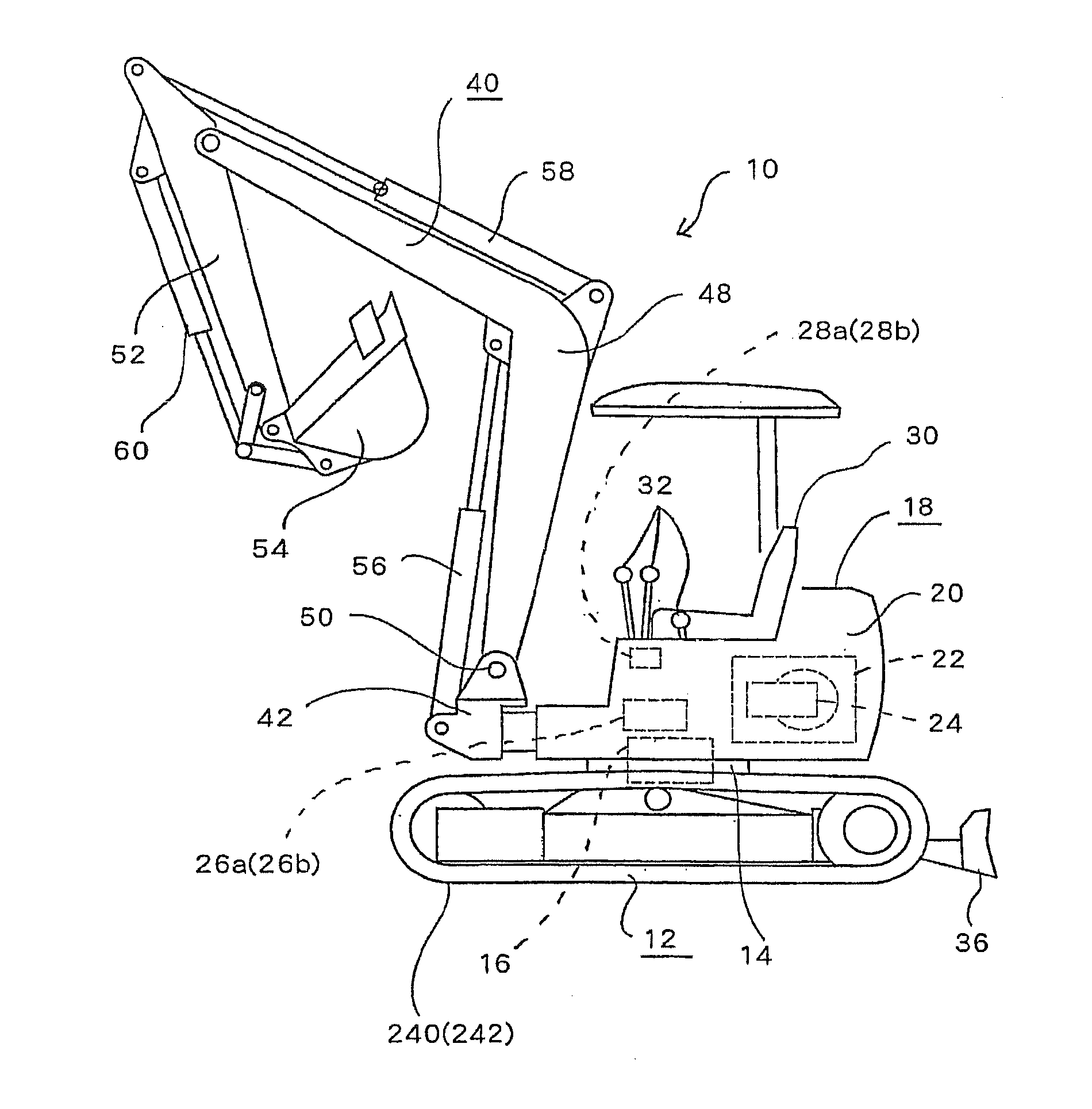
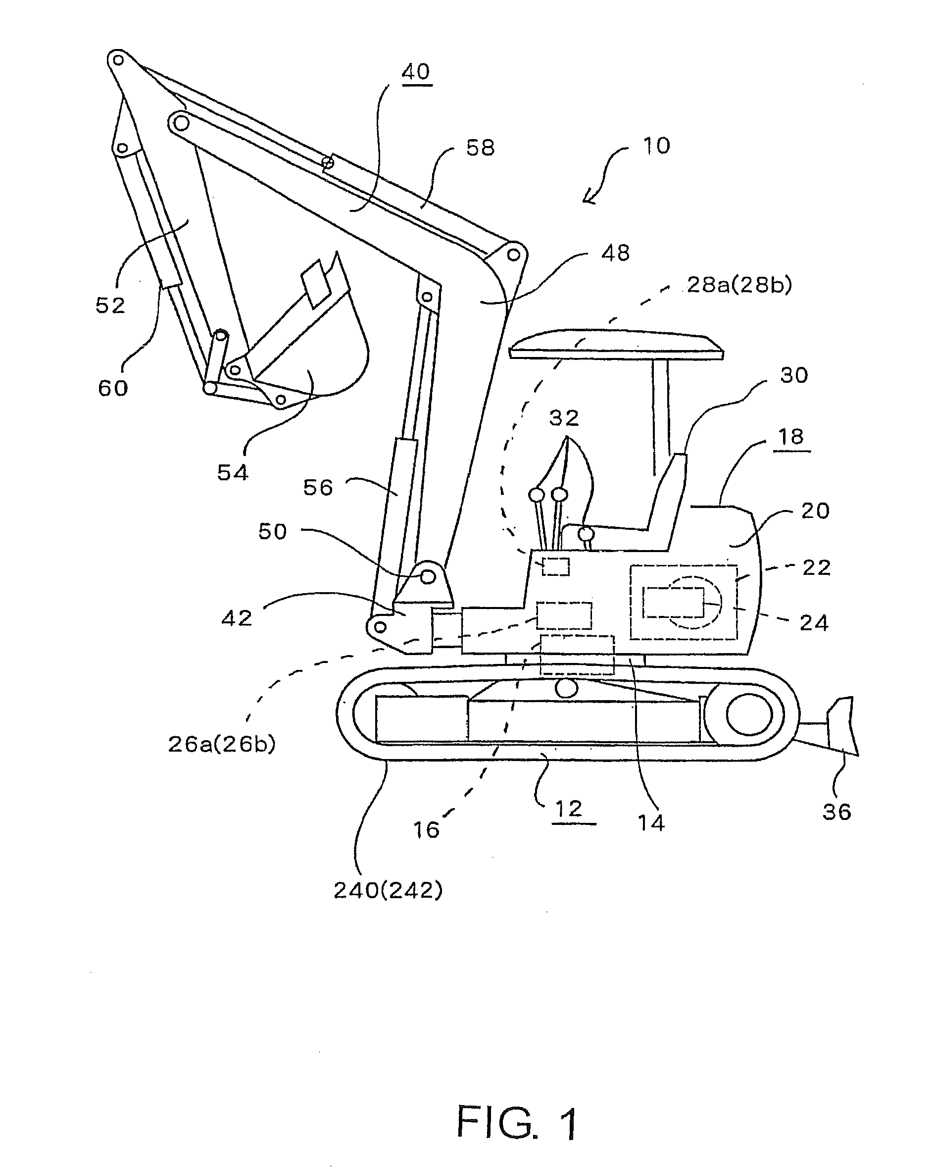
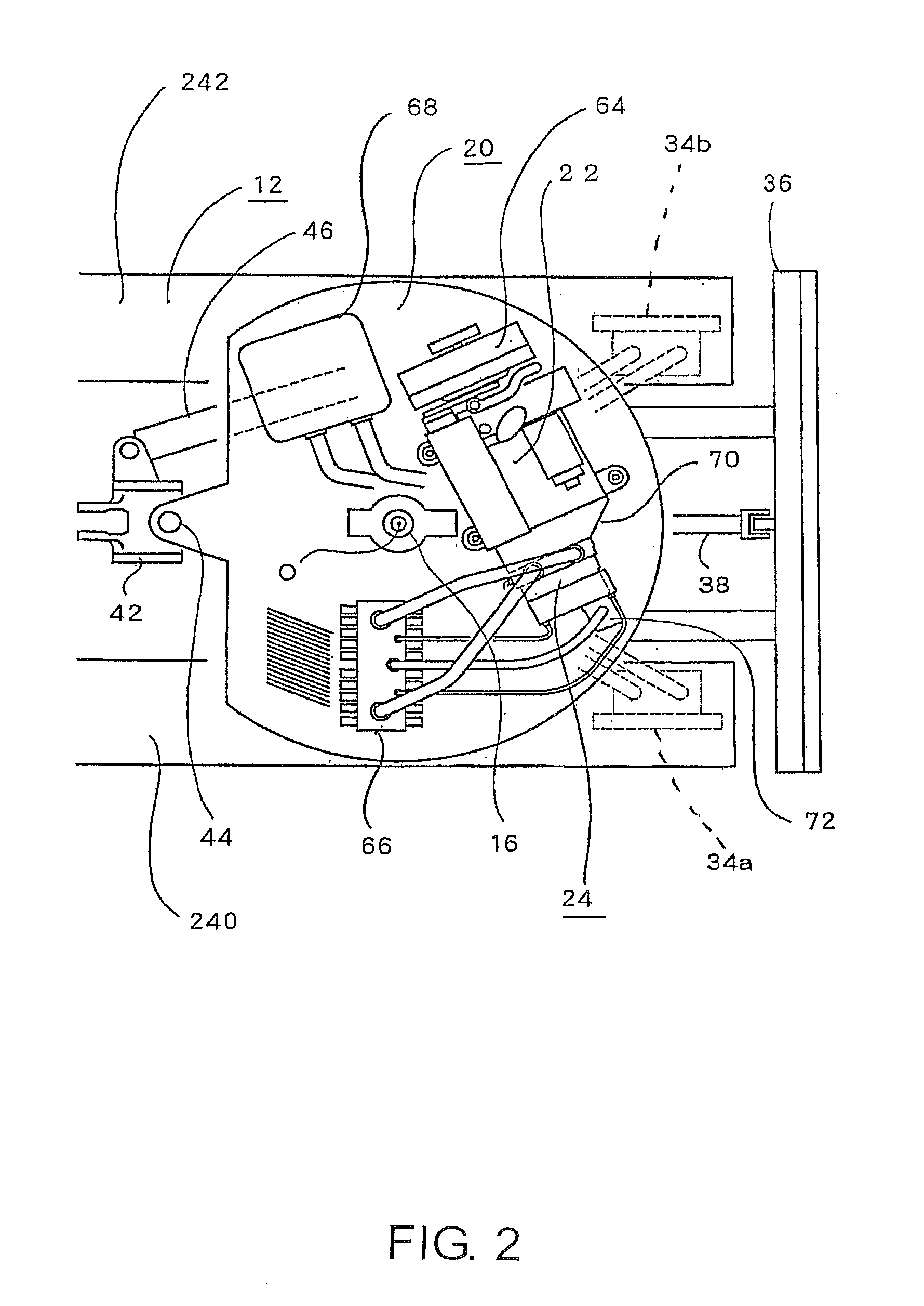
[0030]Embodiments of the present invention will be described in detail below using the drawings. FIG. 1 to FIG. 15 are drawings showing the present invention. As shown in FIG. 1, a excavator 10, being a hydraulically-powered working vehicle of this embodiment, comprises a travel unit 12 including a pair of left and right crawler belts 240, 242, a rotation platform 14 arranged at a middle part of the travel unit 12, a turning motor 16 provided at a middle part of the rotation platform 14, an upper structure 18 that is a turning section provided at an upper side of the travel unit 12 capable of being turned about a vertical turning axis O (FIG. 2) by the rotation platform 14, and an excavation section 40, being a working section supported on the upper structure 18.
[0031]Also, the pair of left and right crawler belts 240, 242 are a left side crawler belt 240, being a one side travel section, and a right side crawler belt 242, being an other side travel section, capable of being respect...
second embodiment
[0093]FIG. 16 is a hydraulic circuit diagram for a pump unit 24 of a With the example shown in FIG. 16, differing from the structure that was shown in FIG. 4 etc. described above, a fourth received pressure chamber 198 constituting each balanced piston mechanism 94, 98, communicates with an oil reservoir 110. Also, the third pressure receiving chamber 202 constituting each balanced piston mechanism 94, 98 is connected to the secondary side of a respectively corresponding variable pressure reducing valve 114, which is a variable control pressure reducing valve. At the time of normal operation, the variable pressure reducing valve 114 is controlled so that in a steady state of the directional control valves 26a, 26b (refer to FIG. 3) at the operating position, a set pressure ΔPLS that is set in advance, equivalent to working oil differential pressure arising before and after passing through the directional control valves 26a, 26b, is introduced at the third pressure receiving chamber...
PUM
 Abstract
Description
Claims
Application Information