Producing universally sharp images

a technology of universal sharpness and image, applied in the field of image and video photography, can solve the problems of limiting the usefulness of non-microscopic applications, requiring a high computational load for each output image computed, and difficult to image three-dimensional specimens

a technology of universal sharpness and image, applied in the field of image and video photography, can solve the problems of limiting the usefulness of non-microscopic applications, requiring a high computational load for each output image computed, and difficult to image three-dimensional specimens

US20120098947A1Inactive Publication Date: 2012-04-26WILKES DAVID ROBERT

Image

  • Producing universally sharp images
  • Producing universally sharp images
  • Producing universally sharp images

Examples


Embodiment Construction

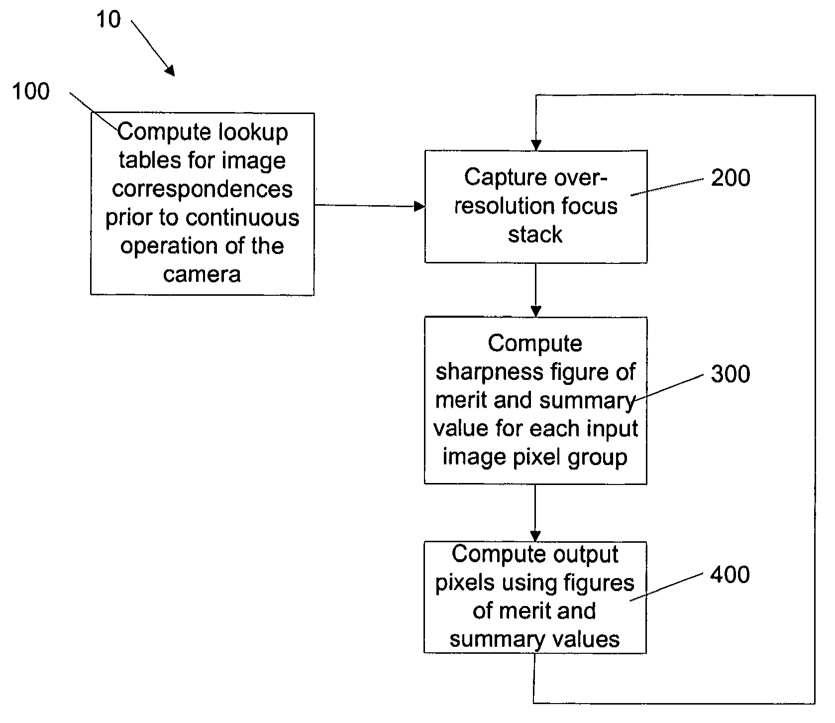
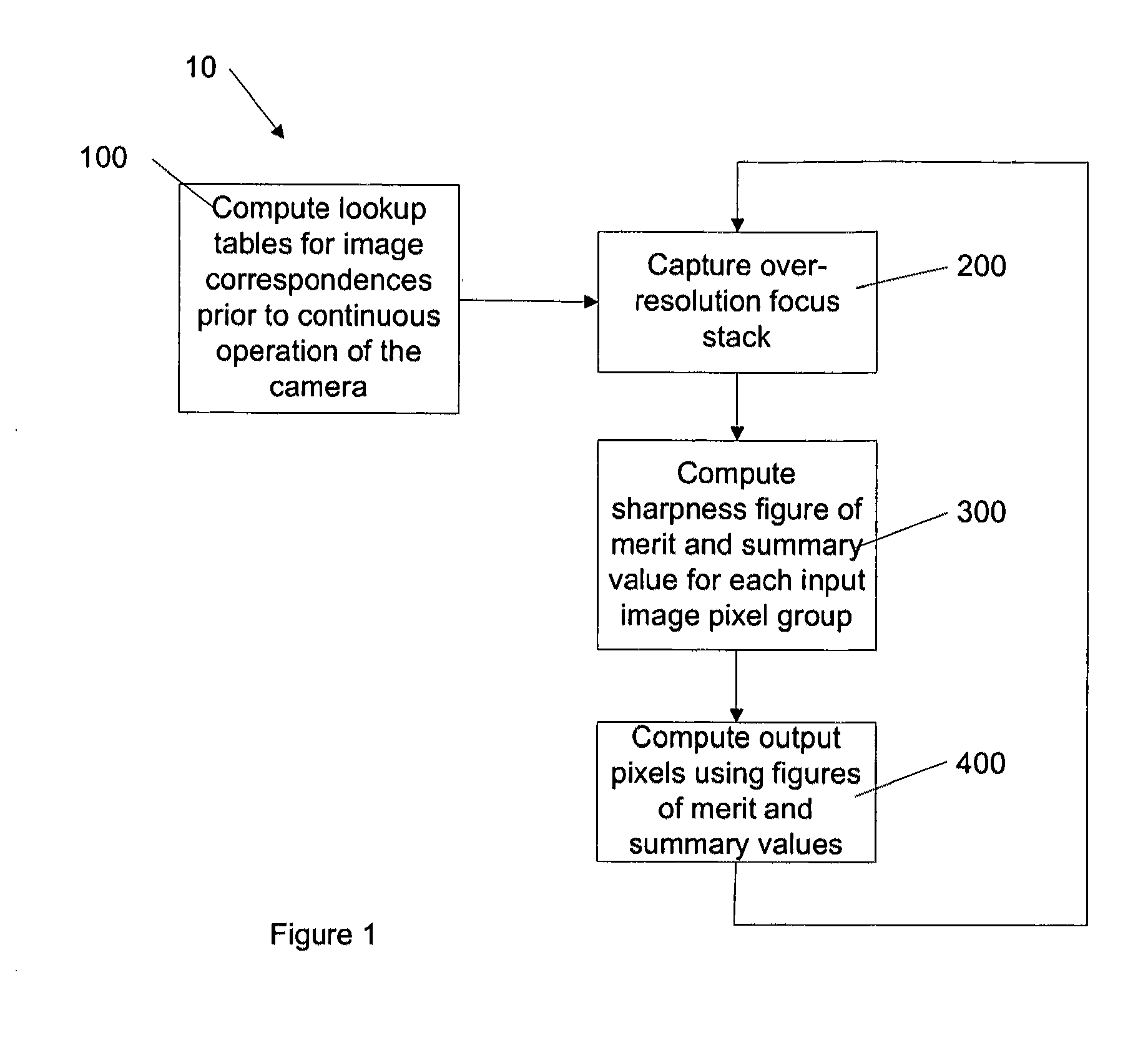
[0024]Turning now to FIG. 1, a flow chart showing a method of combining images to produce a universally sharp output image is shown and is generally identified by reference numeral 10. As will be discussed below, input images are captured and are defined by input pixels. The input images are captured at a higher resolution than the desired resolution of the output image. As such, a group of input pixels is identified as corresponding to each one of the output pixels. A universally sharp output image is made of output pixels each having an output pixel value that is sharply in focus.

[0025]Accordingly, method 10 begins with computing lookup tables for image correspondences between each output pixel and each group of input pixels (step 100). A focus stack of input images is captured using a focus stack capture program, wherein each input image has a different focus setting (step 200). A sharpness figure of merit and a summary pixel value are calculated for each group of input pixels (s...


PUM


Abstract

A method for producing an output image defined by output pixels comprises capturing a focus stack of input images, each input image defined by input pixels and having a resolution higher than the output image, determining a group of input pixels in each input image corresponding to one of the output pixels, calculating a figure of merit and a summary pixel value for each group of input pixels, and computing a value for each output pixel by mathematically combining the figures of merit and the summary pixel values corresponding to each output pixel. The output image values are calculated such that the entire output image is sharply in focus.

Description

[0001]I claim priority to my provisional application No. 61 / 394,942.FIELD OF THE INVENTION[0002]The present invention relates generally to image and video photography and in particular, to a method and system for producing a universally sharp image.BACKGROUND OF THE INVENTION[0003]Under certain conditions, it is a challenge in the field of image and video photography to capture images in which the entire subject matter is sharply in focus. For example, in the field of endoscopy, images of human internal organs are captured and can contain pairs of regions which are at significantly different distances from the camera lens, exceeding its depth of focus. As a result, in the captured images, one of the regions will be out of focus. Another example is in the field of microscopy, where it is difficult to image three-dimensional specimens so that all portions of the specimen are in focus in the same image, given the extremely shallow depth of field of conventional microscope images.[0004]...

Claims


Application Information

Patent Timeline
26 Apr 2012
Publication
US20120098947A1
IPC
H04N5/228; H04N7/18
CPC
H04N5/23212; H04N2005/2255; H04N7/183; H04N5/2356; H04N23/555; H04N23/676; H04N23/743
Inventors
WILKES, DAVID ROBERT