Infrared binocular system with dual diopter adjustment

a binocular system and diopter technology, applied in the field of infrared binocular systems with dual diopter adjustment, can solve problems such as the gap between the left eye and the binocular ey

Inactive Publication Date: 2012-04-26
FLIR SYST INC
View PDF16 Cites 66 Cited by
  • Summary
  • Abstract
  • Description
  • Claims
  • Application Information

AI Technical Summary

Problems solved by technology

The difference between these viewpoints can result in binocular disparity between the left eye and the right eye retinal images, which may, for those with normal binocular vision, provide cues for stereoscopic depth perception of the scene or a three-dimensional (3D) image.

Method used


Image

  • Infrared binocular system with dual diopter adjustment
  • Infrared binocular system with dual diopter adjustment
  • Infrared binocular system with dual diopter adjustment

Examples


example 1

Exemplary Infrared Binocular System

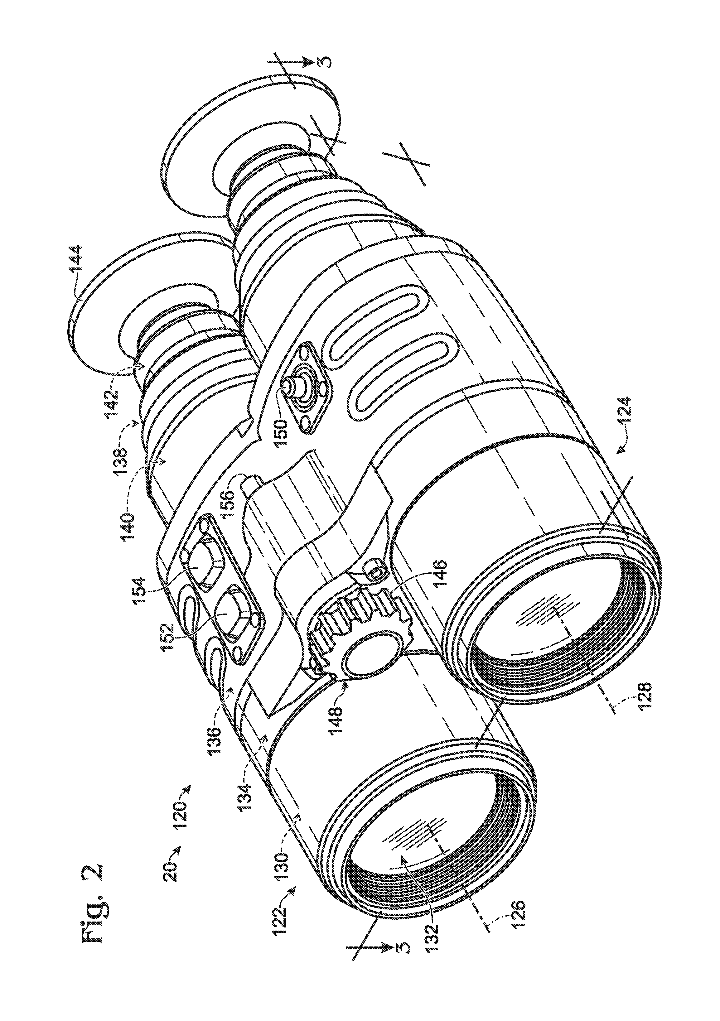
[0073]This example describes an exemplary embodiment of an infrared binocular system 120; see FIGS. 2-6.

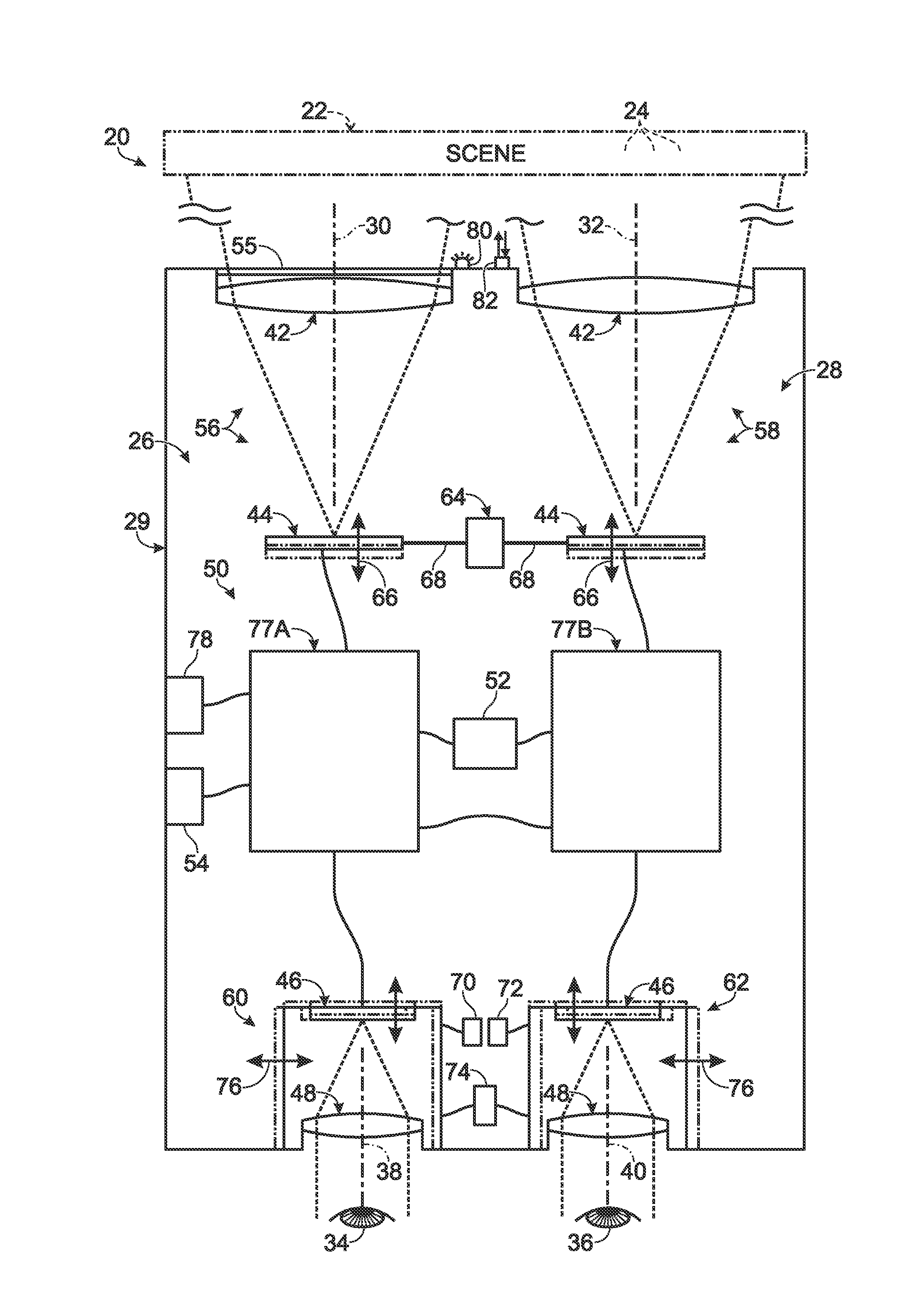
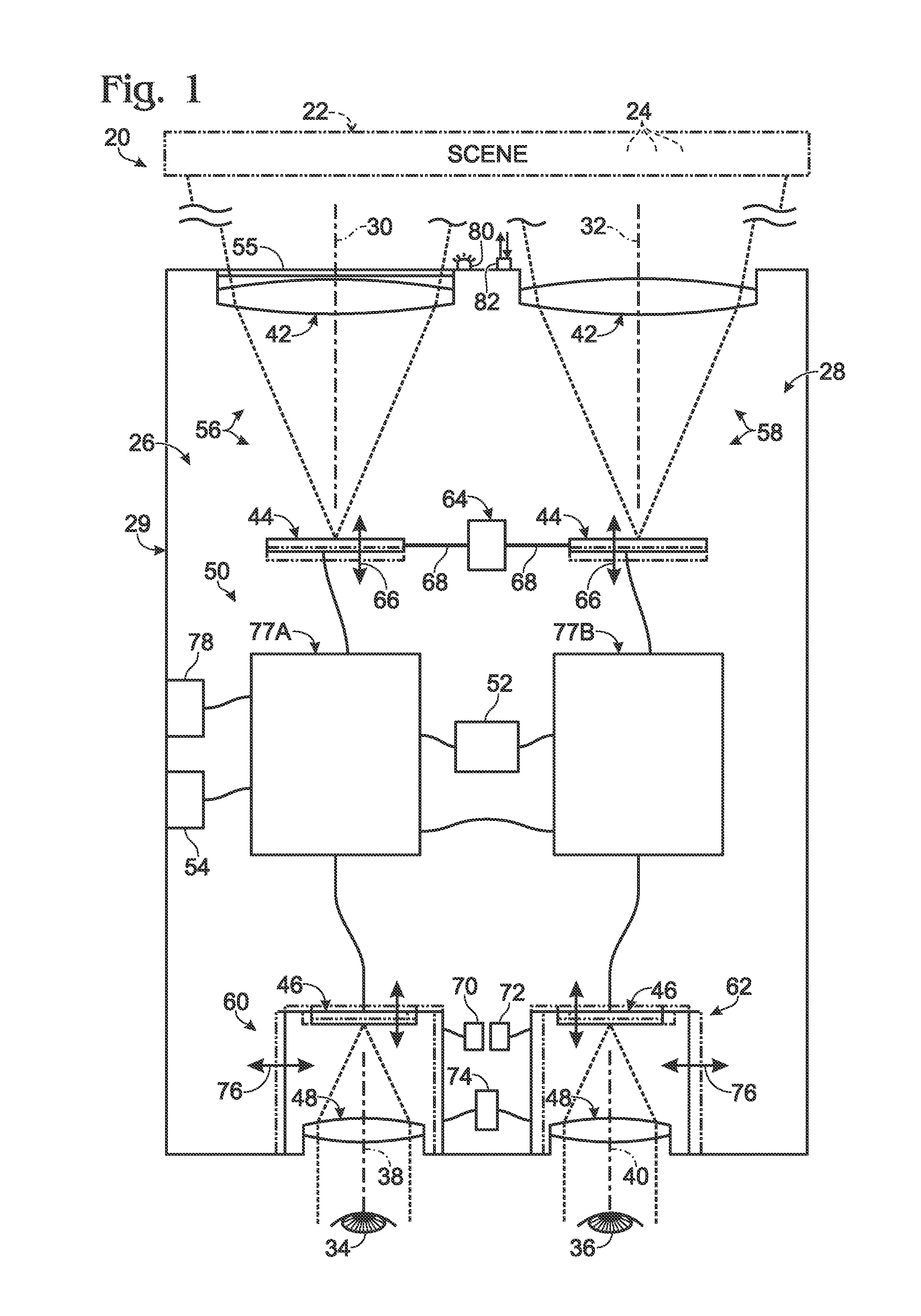
[0074]FIGS. 2 and 3 show respective isometric and sectional views of binocular system 120. The system includes a pair of monocular assemblies 122, 124 each capable of detecting incident infrared radiation received on input optical axes 126, 128 from a distant scene and presenting a visible light representation of the detected radiation to an observer. The monocular assemblies are mirror images of one another and contain substantially identical components.

[0075]Each assembly includes a thermal camera 130. The camera receives and focuses incident infrared radiation using objective 132. The radiation is focused onto a focal plane array 134 of the camera, which creates a signal (i.e., image / video data) representative of the detected radiation, which is communicated to a controller subunit 136.

[0076]Controller subunit 136 may process the signal (e.g.,...

example 2

Exemplary Interpupillary Adjustment Mechanism

[0083]This example describes another exemplary embodiment of an infrared binocular system 220 with an alternative interpupillary adjustment mechanism 222; see FIG. 7.

[0084]The binocular system includes a pair of visualization units 224, 226 each hooked onto and slidable on a pair of rails 228. The visualization units are connected via a thumbwheel assembly 230 that forms a span between the two units. Both ends of the thumbwheel assembly are in threaded engagement, indicated at 232, with a visualization unit. Rotation of the thumbwheel changes the length of the span between the units, which coordinately drives the units closer together or farther apart, depending on the direction of thumbwheel rotation. In other cases, one of the visualization units may be fixed and the other movable.

example 3

Exemplary Binocular System with Separate Units for Detection and Image Display

[0085]This example describes an exemplary binocular system 320 divided into separate units; see FIG. 8.

[0086]System 320 includes a camera unit 322 and a presentation unit 324. The camera unit is equipped with at least two cameras 326, 328 adapted to create left and right video signals, which are communicated to the presentation unit for presentation of left and right videos by displays 330, 332 based on the video signals. Alternatively, or in addition, the left and right video signals may be communicated to a 3D display. One or both units 322, 324 may include a controller 334, 336 that manipulates the video signals and / or drives presentation of video images by the displays. Units 322, 324 may communicate with one another via a wired or wireless mechanism, indicated at 338.

[0087]The units may be movable independently of one another along and / or about multiple axes. With this arrangement, the camera unit can...


PUM


Abstract

Binocular system, including method and apparatus, for viewing a scene. The system may comprise a left camera and a right camera that create left and right video signals from detected optical radiation. At least one of the cameras may include a sensor that is sensitive to infrared radiation. The system also may comprise a left display and a right display arranged to be viewed by a pair of eyes. The left and right displays may be configured to present respective left video images and right video images formed with visible light based respectively on the left and right video signals.

Description

CROSS-REFERENCES TO PRIORITY APPLICATIONS[0001]This application is based upon and claims the benefit under 35 U.S.C. §119(e) of U.S. Provisional Patent Application Ser. No. 61 / 406,059, filed Oct. 22, 2010, and U.S. Provisional Patent Application Ser. No. 61 / 433,370, filed Jan. 17, 2011, each of which is incorporated herein by reference in its entirety for all purposes.INTRODUCTION[0002]Various optical devices are available for providing magnified views of distant objects or scenes. These devices may be distinguished by whether they are based on lenses, mirrors, or both, by whether they have one eyepiece or two, by whether they are handheld or mounted, and so on. Common handheld devices include monoculars, bioculars, and binoculars. Monoculars have one imager and one eyepiece. A user who uses this device may see an altered (e.g., magnified) view of the scene in one eye and an unaided view of the scene in the other eye. Bioculars have one imager and two eyepieces. Here, the user's two...

Claims


Application Information

Patent Timeline
Patent Type & Authority Applications(United States)
IPC IPC(8): H04N5/33
CPCH04N5/2258H04N5/33H04N5/272H04N5/23212G02B23/10G02B23/12G02B23/18H04N23/53H04N23/45H04N23/55H04N23/67H04N23/63G06F18/22H04N23/51H04N23/69G06T11/001G06T11/60
Inventor HANSEN, JOEL A.MILLER, JOHN L.WORLEY, M. STUARTJOLIVET, NOEL
Owner FLIR SYST INC
Why Eureka
Try Eureka