Electronic camera

a technology of electronic cameras and cameras, applied in the field of electronic cameras, can solve the problems of more electric power consumption and electric power waste, and achieve the effect of preventing electric power from being wasted

Inactive Publication Date: 2012-04-26
NIKON CORP
View PDF5 Cites 13 Cited by
  • Summary
  • Abstract
  • Description
  • Claims
  • Application Information

AI Technical Summary

Benefits of technology

[0007]A proposition of the present embodiment is to provide an electronic camera capable of preventing electric power from being wasted when a plurality of image processing units is used.

Problems solved by technology

In contrast, a large amount of electric power is consumed in the image processing for obtained image data, and thus, if image processing is performed by using the above-described two image processing units, more electric power is consumed.
Furthermore, the provision of two image processing units is effective for image processing at the time of continuous shooting and movie shooting, but at the time of shooting of a still image, image processing can be performed by one of the image processing units and the other image processing unit does not perform any image processing, and thus, electric power is wasted.

Method used


Image

  • Electronic camera
  • Electronic camera
  • Electronic camera

Examples


first embodiment

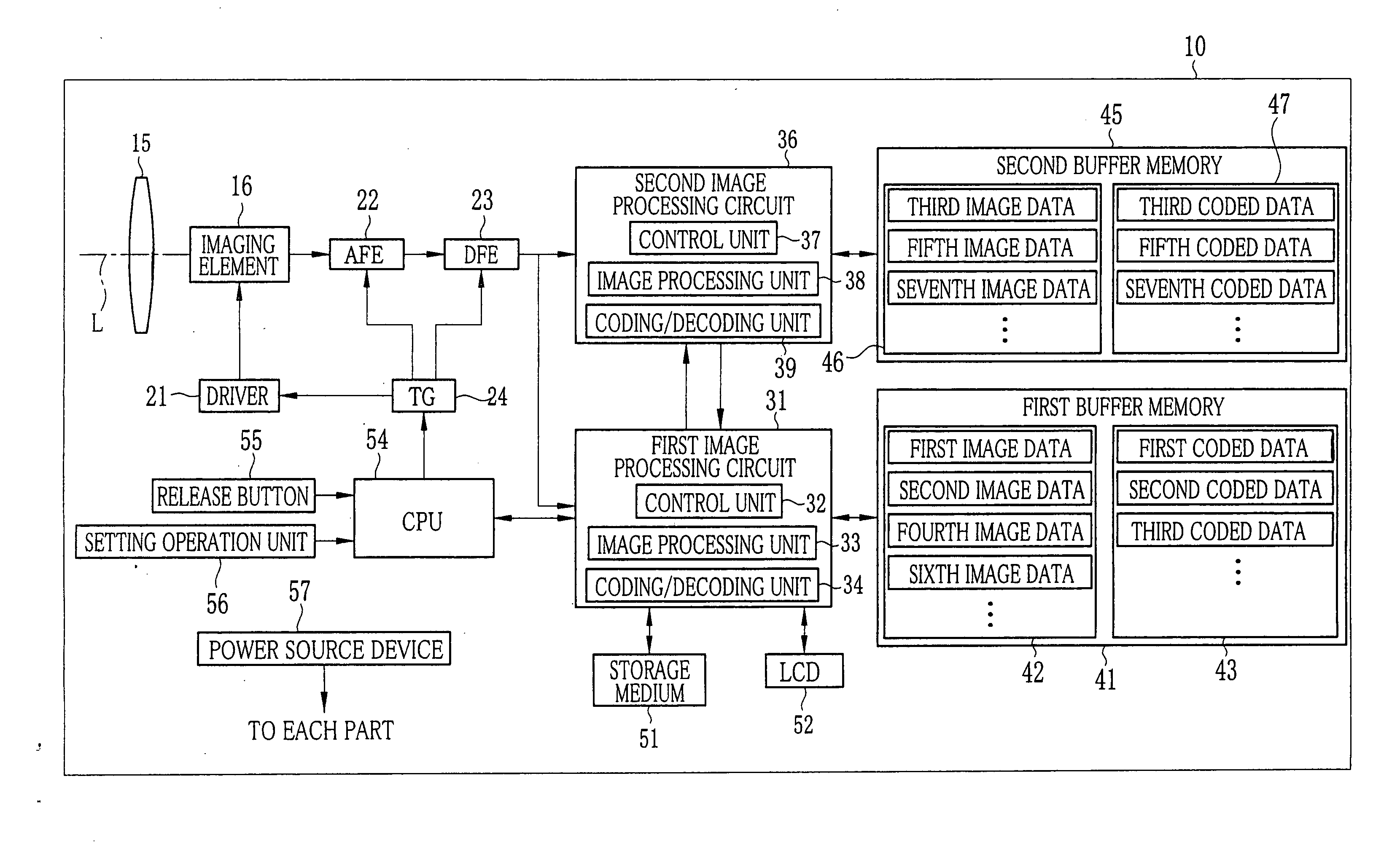
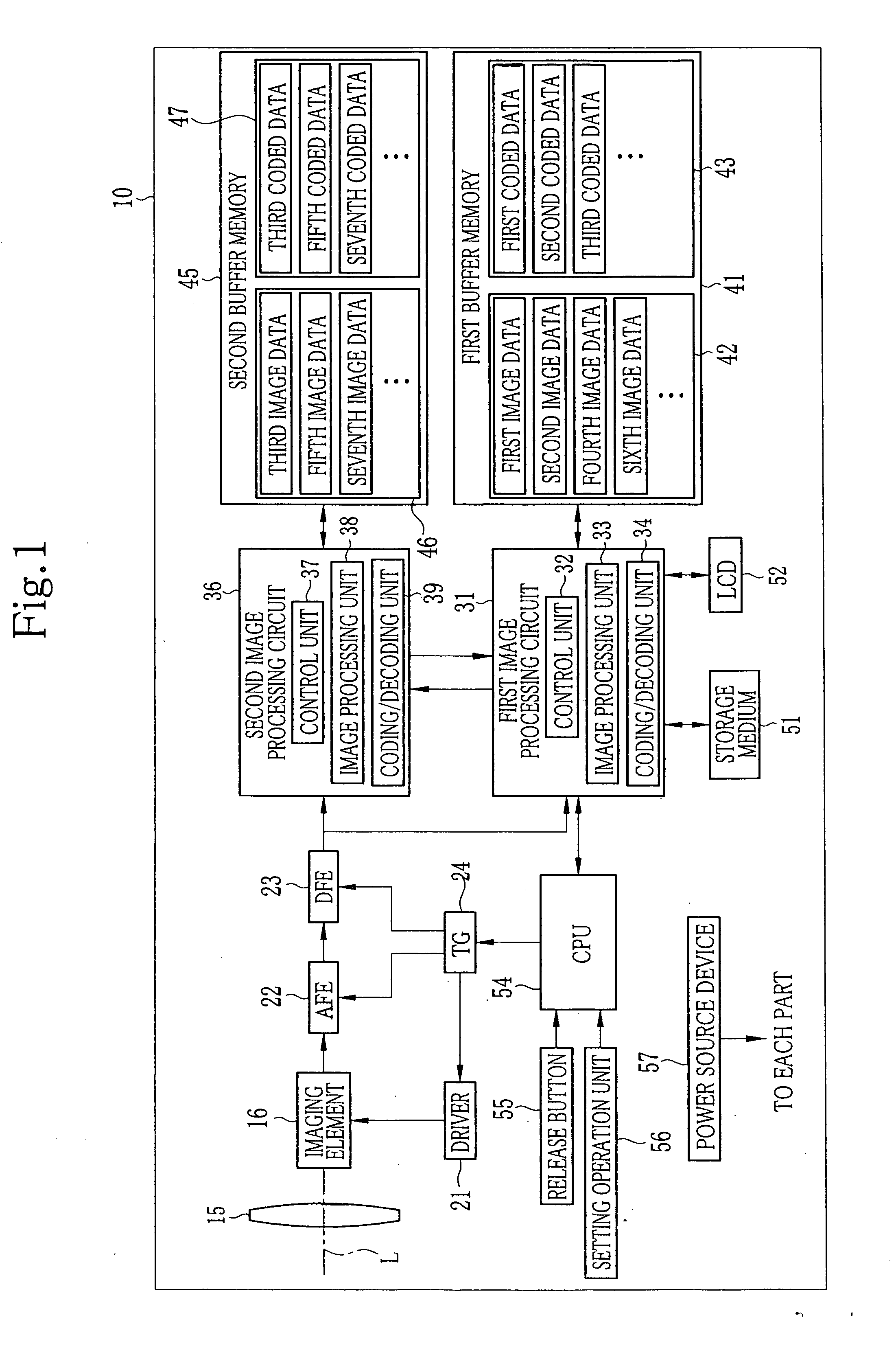
[0026]FIG. 1 shows an example of a digital camera using the present invention. It is made possible for a digital camera 10 of the present invention to perform movie shooting to obtain a moving image in addition to still image shooting to obtain one still image at the time of operation of a release button 55, to be described later, continuous shooting to continuously obtain a predetermined number of still images at regular intervals at the time of full-press operation of the release button 55, to be described later. Explanation will be given below on the assumption that a mode to perform still image shooting is referred to as a still image mode, a mode to perform continuous shooting as a continuous shooting mode, and a mode to perform movie shooting as a moving image mode. Furthermore, explanation is given on the assumption that an action to obtain an image by the digital camera 10 is referred to as shooting and the internal processing of the digital camera 10 performed at the time o...

second embodiment

[0059]A second embodiment of the present invention will be explained below using the drawings. Meanwhile, the second embodiment is a modification of the first embodiment in which the basis for determination of control is different, and thus, only parts different from those in the first embodiment are explained. Furthermore, the same configuration as that of the first embodiment is explained by using the same symbol.

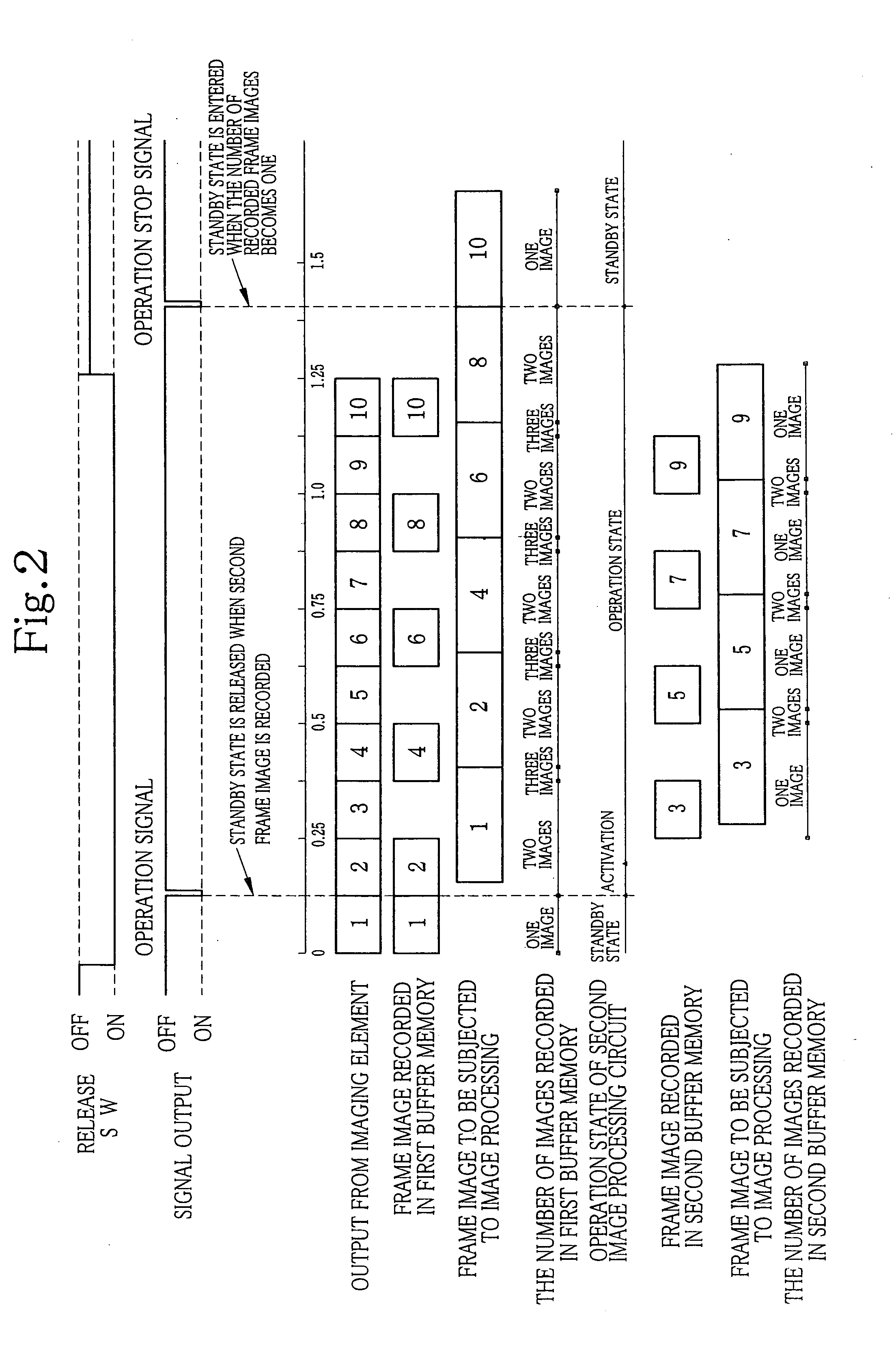
[0060]Next, the flow of processing in the first image processing circuit 31 and the second image processing circuit 36 when shooting is performed in the continuous shooting mode in the second embodiment is explained using the timing chart in FIG. 3. Meanwhile, in the timing chart in FIG. 3, a case is explained, where 10 images are shot continuously in the continuous shooting mode at a frame rate value of 8 fps. Each frame image in FIG. 3 corresponds to each piece of image data shown in FIG. 1. That is, the frame image 1 corresponds to the first image data shown in FIG. 1 ...


PUM


Abstract

An imaging element which continuously outputs image data obtained by photoelectrically converting object light, a buffer memory which temporarily stores image data being output from the imaging element, a plurality of image processing units which are capable of performing image processing on image data output from the imaging element, and a control unit which causes an image processing unit of the plurality of image processing units to operate based on a number of pieces of the image data stored in the buffer memory when the image data is output continuously from the imaging element, in which the image processing unit performs image processing on each piece of image data output continuously.

Description

CROSS REFERENCE TO RELATED APPLICATIONS[0001]This application is based upon and claims the benefit of priority from Japanese Patent Application No. 2010-094317, filed on Apr. 15, 2010, the entire contents of which are incorporated herein by reference.BACKGROUND[0002]1. Field[0003]The present application relates to an electronic camera that performs image processing on image data obtained by shooting.[0004]2. Description of the Related Art[0005]Conventionally, in an electronic camera such as a digital camera, there are provided a continuous shooting mode in which a plurality of still images is obtained continuously based on a frame rate set in advance, a moving image mode in which a moving image is obtained, etc., in addition to a shooting mode in which one still image is obtained. In a digital camera comprising such a continuous shooting mode and a moving image mode, image data is output at regular intervals from an imaging element, and thus, if processing capacity relating to image...

Claims


Application Information

Patent Timeline
Patent Type & Authority Applications(United States)
IPC IPC(8): H04N5/76H04N5/228H04N5/225H04N5/232H04N101/00
CPCH04N1/2141H04N2101/00H04N5/23241H04N23/64H04N23/667
Inventor TSUDA, YUTAKA
Owner NIKON CORP
Why Eureka
Try Eureka