
Image forming apparatus

Inactive Publication Date: 2012-04-26
CANON KK
View PDF3 Cites 24 Cited by
  • Summary
  • Abstract
  • Description
  • Claims
  • Application Information

AI Technical Summary

Benefits of technology

[0011]It an object of the present invention to provide a developing apparatus in which a toner agglomeration mass is not easil

Problems solved by technology

In the case of the structure in which the developer is circulated through the reception bridging portion, the developer may not be transferred in the reception bridging portion with the result of stagnation of the developer, in some cases.
If the stagnation of the developer occurs, charging non-uniformity of the toner may result, which may lead to an image defect, developer overflow, screw locking or the like.
However, only by the provision of the magnetic member on the feeding screw, the developer feeding performance between the developer chamber and the stirring chamber is not always assisted, and therefore, the stagnation of the developer in the reception bridging portion is still possible.
On the other hand, with the structure disclosed in Japanese Laid-open Patent Application Hei 9-319223, the following problem may arise.
When the use amount of the toner is small as in the case that a great number of low image density output images are formed, toner deterioration occurs such as removal or embedding of externally added material, or the like.
The reduction of the carrying amount me cause an image defect such as density non-uniformity.
In such a case, however, it is not avoidable that a shear plane is produced due to a flow speed difference the developer between the developer confined by the magnet and the developer fed by the feeding screw.
As a result, a toner agglomeration mass is produced at the shear plane, and if the toner agglomeration mass is carried to the blade portion, the developer coating amount on the developing sleeve becomes insufficient.

Method used


Image

  • Image forming apparatus
  • Image forming apparatus
  • Image forming apparatus

Examples


embodiment 1

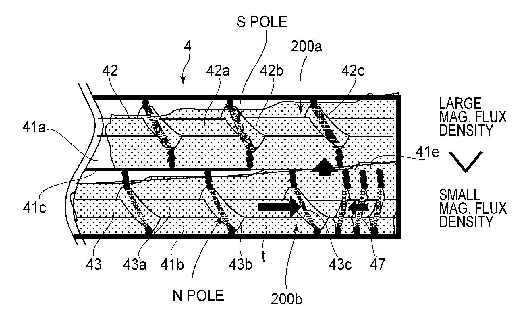
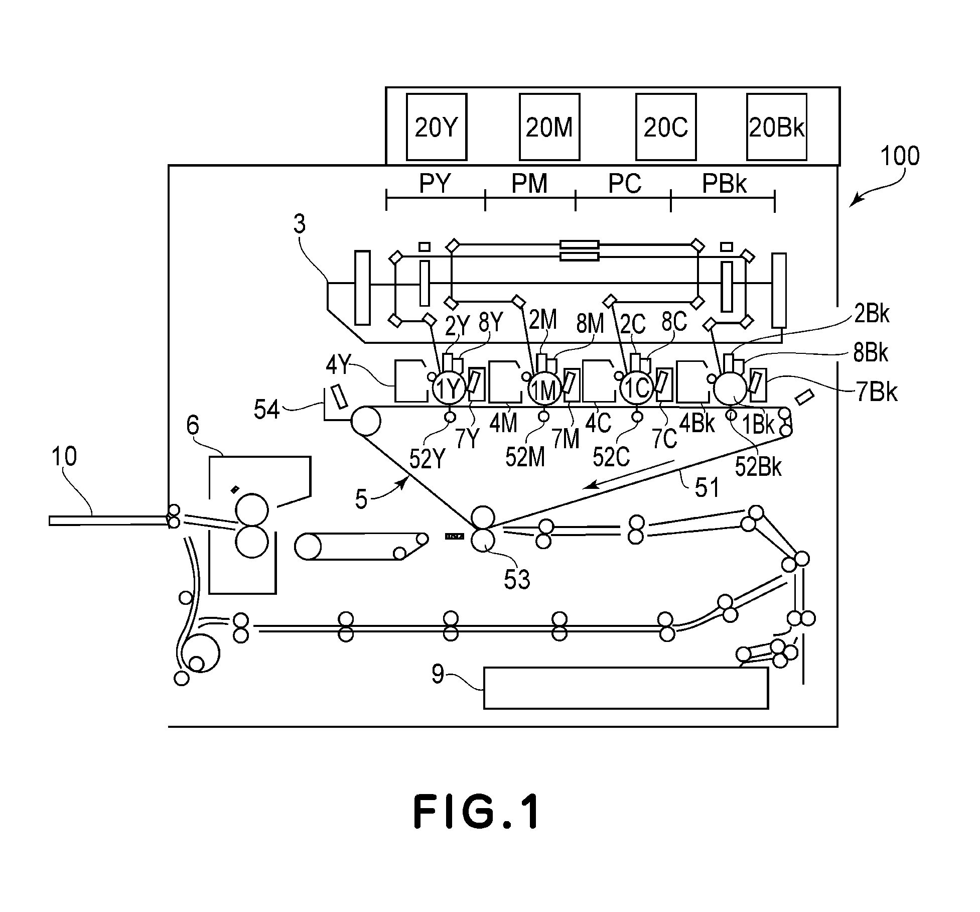
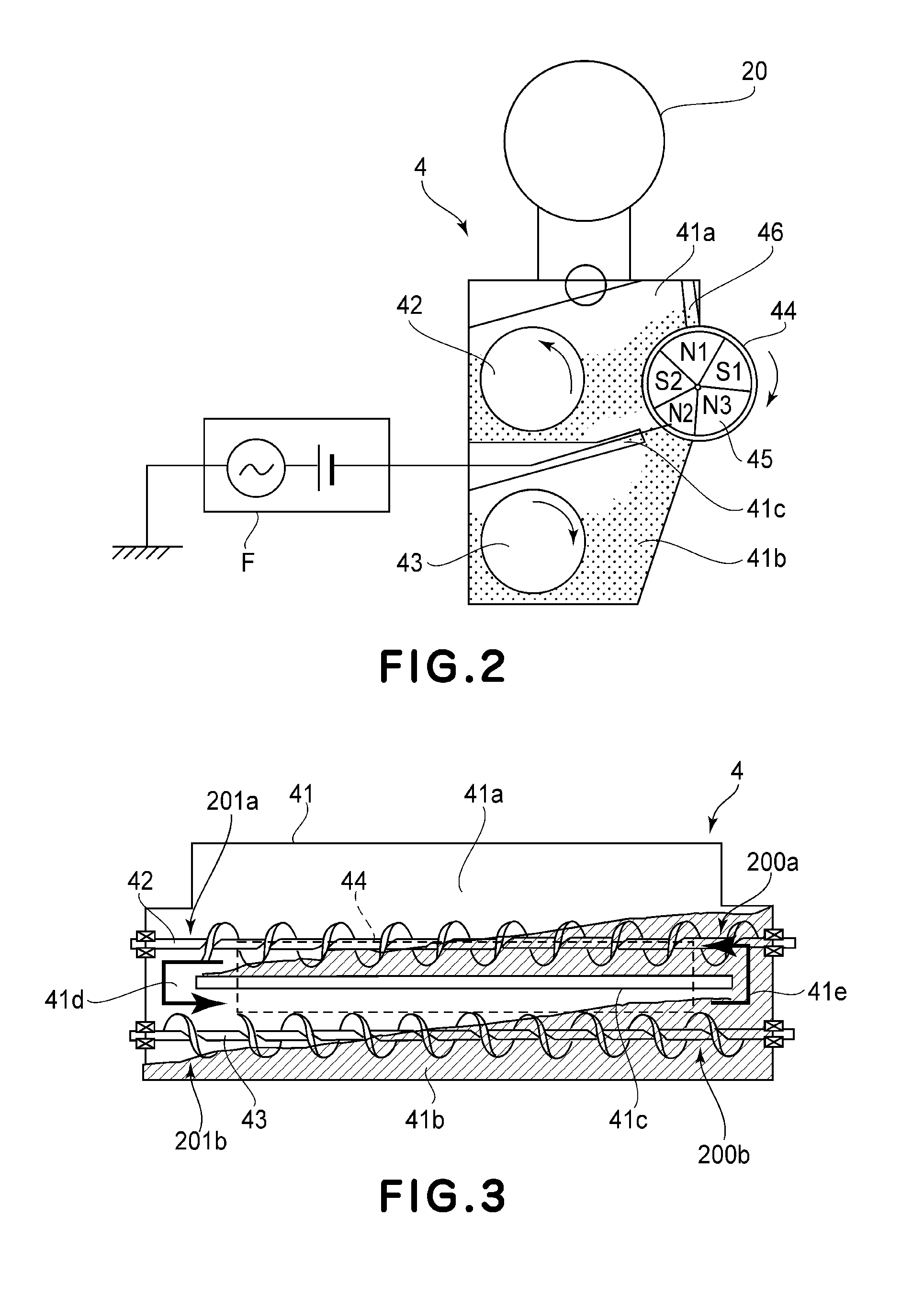
[0024]First, referring to FIGS. 1-5, the first preferred embodiment of the present invention is described. To begin with, the overall structure of the image forming apparatus in this embodiment is described with reference to FIG. 1.

[Image Forming Apparatus]

[0025]An image forming apparatus 100 forms images based on the information of an image to be formed. The information is given to the image forming apparatus by a reading device connected to the main assembly of the image forming apparatus 100, or a host device, such as a personal computer, which is in connection to the main assembly of the apparatus 100 in such a manner that communication is possible between the host device and the main assembly of the apparatus 100. The image forming apparatus 100 in this embodiment can electrophotographically form full-color images on recording medium (sheet of recording paper, a sheet of plastic, piece of fabric, etc.). The full-color image is based on four primary colors, more specifically, ye...

embodiment 2

[0081]Next, referring to FIGS. 8-10, the second preferred embodiment of the present invention is described. Since the image forming apparatus in this embodiment is the same in basic structure as the one in the first embodiment, its overall structure is not going to be described here. This embodiment is related to an image formation system which can be reduced in the speed of its developer conveyance screws to ensure that a toner image is properly fixed when thick recording paper is used as recording medium.

[0082]Some image forming apparatuses can be reduced in productivity to ensure that a toner image is properly fixed when recording medium which is larger in basis weight than ordinary recording medium, so-called coated paper, that is, glossy medium, or the like, is used as recording medium. Reducing an image forming apparatus in productivity means reducing the image forming apparatus in overall operational speed. In other words, it means that the developing device 4 also is reduced...


PUM


Abstract

A developing device comprising a developer carrying member for carrying the developer containing non-magnetic toner and magnetic carrier to a position where said developer carrying member is opposed to an image bearing member; a developing container including a first chamber for accommodating a developer to be supplied to said developer carrying member, a second chamber provided below said first chamber, and a pair of transferring portions for circulating the developer between said first chamber and said second chamber; a first feeding member and a second feeding member, rotatably provided, in said first chamber and said second chamber, respectively, for stirring and feeding the developer; and a magnetic member provided at least on said first feeding member, wherein said magnetic member is provided in a region opposing at least one of said transferring portions where the developer is scooped from said second chamber into said first chamber.

Description

FIELD OF THE INVENTION AND RELATED ART[0001]The present invention relates to a developing device for visualizing a latent image formed on an image bearing member by a developer, and an image forming apparatus of an electrophotographic type or an electrostatic recording type, such as a copying machine, a laser beam printer, a facsimile machine, a complex machine of them, or the like.[0002]As a color image forming apparatus, a tandem type in which a plurality of image forming stations are arranged and a single drum type in which a plurality of developing devices are provided for one image bearing member are known. In the tandem type image forming apparatus, a developing device provided for each image forming station, where a toner image is formed in an associated color. On the other hand, in a single drum type image forming apparatus, different ones of the developing devices are opposed to the single drum to form different color images. For this purpose, the developing devices are sup...

Claims


Application Information

Patent Timeline
IPC IPC(8): G03G15/08
CPCG03G15/0822G03G15/09G03G2215/0844G03G2215/0838G03G2215/0822
Inventor NOGUCHI, AKIHIRONOSE, KATSUYAFUKAMACHI, ASUNA
Owner CANON KK
Learn More