Planar SOFC Stack

a fuel cell and stack technology, applied in the field of planar sofc stacks, can solve the problems of complicated process for interconnection of planar sofc units, difficult to remove any of the planar sofc units, and difficult to replace the broken planar sofc unit with a new on

Inactive Publication Date: 2012-04-26
INST NUCLEAR ENERGY RES ROCAEC
View PDF4 Cites 4 Cited by
  • Summary
  • Abstract
  • Description
  • Claims
  • Application Information

AI Technical Summary

Benefits of technology

[0006]It is the primary objective of the present invention to provide a planar SOFC stack including planar SOFC units that can easily be piled up and replaced with new ones.

Problems solved by technology

Hence, the process for interconnecting the planar SOFC units is complicated.
Furthermore, it is difficult to remove any of the planar SOFC units when it is out of order.
Of course, it is difficult to replace the broken planar SOFC unit with a new one.

Method used


Image

  • Planar SOFC Stack
  • Planar SOFC Stack
  • Planar SOFC Stack

Examples


Embodiment Construction

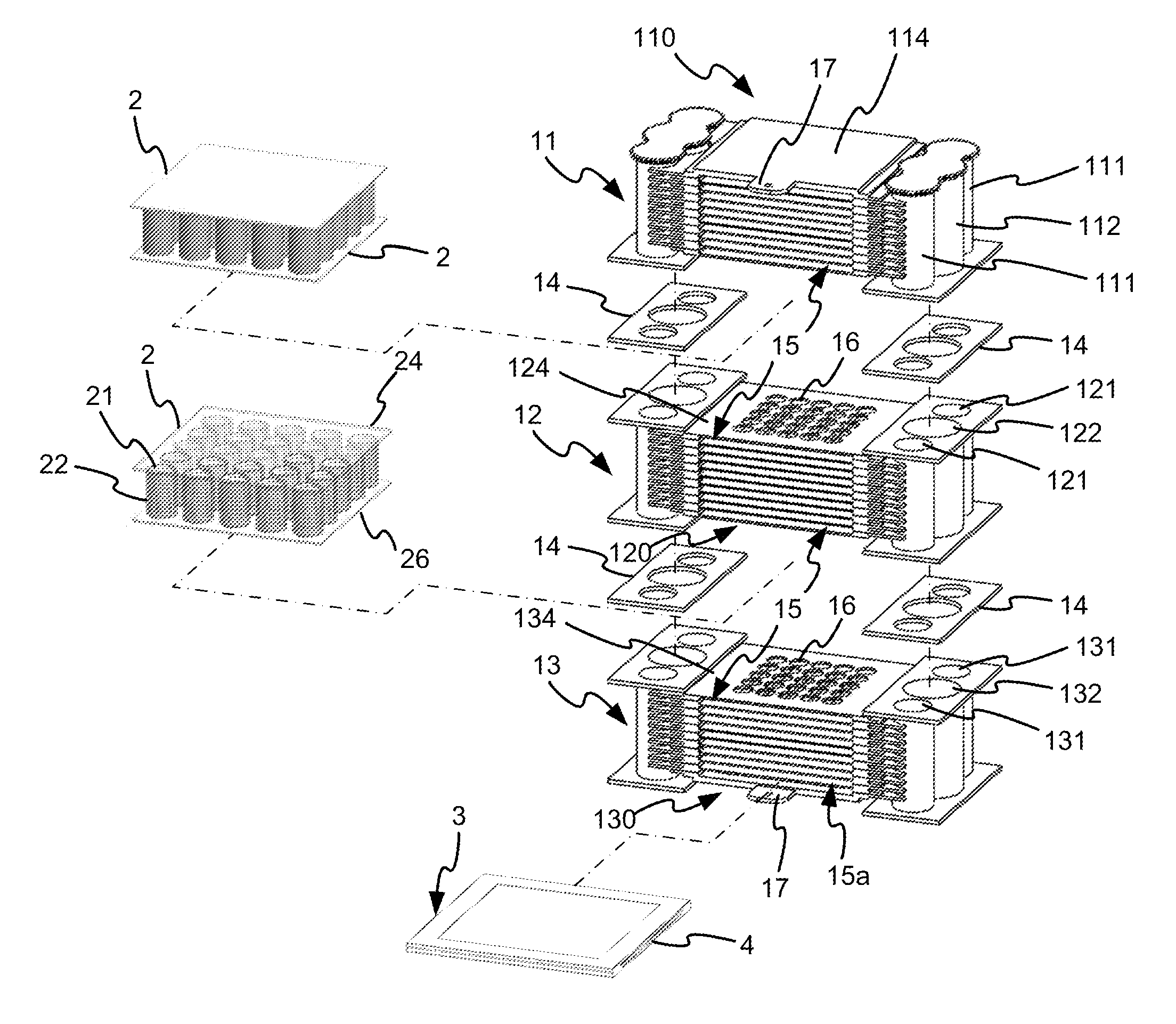
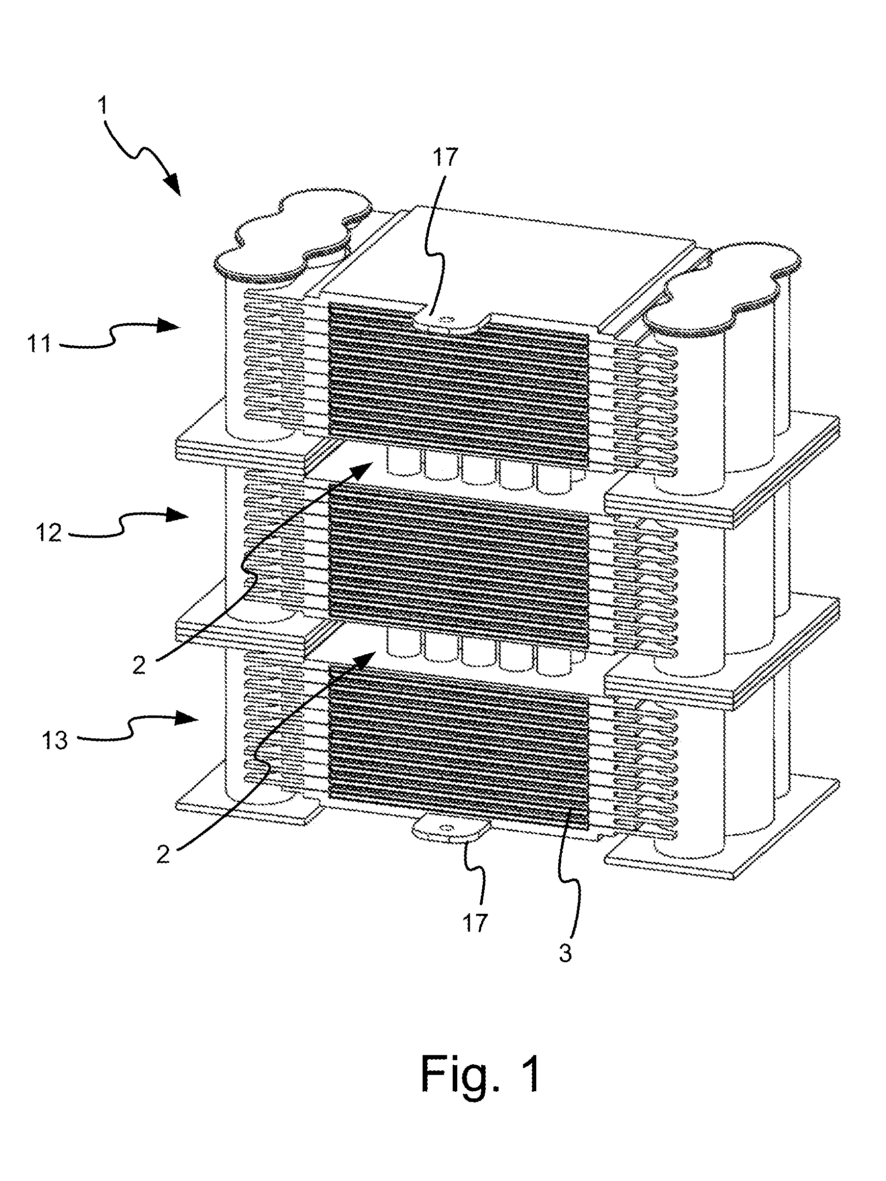
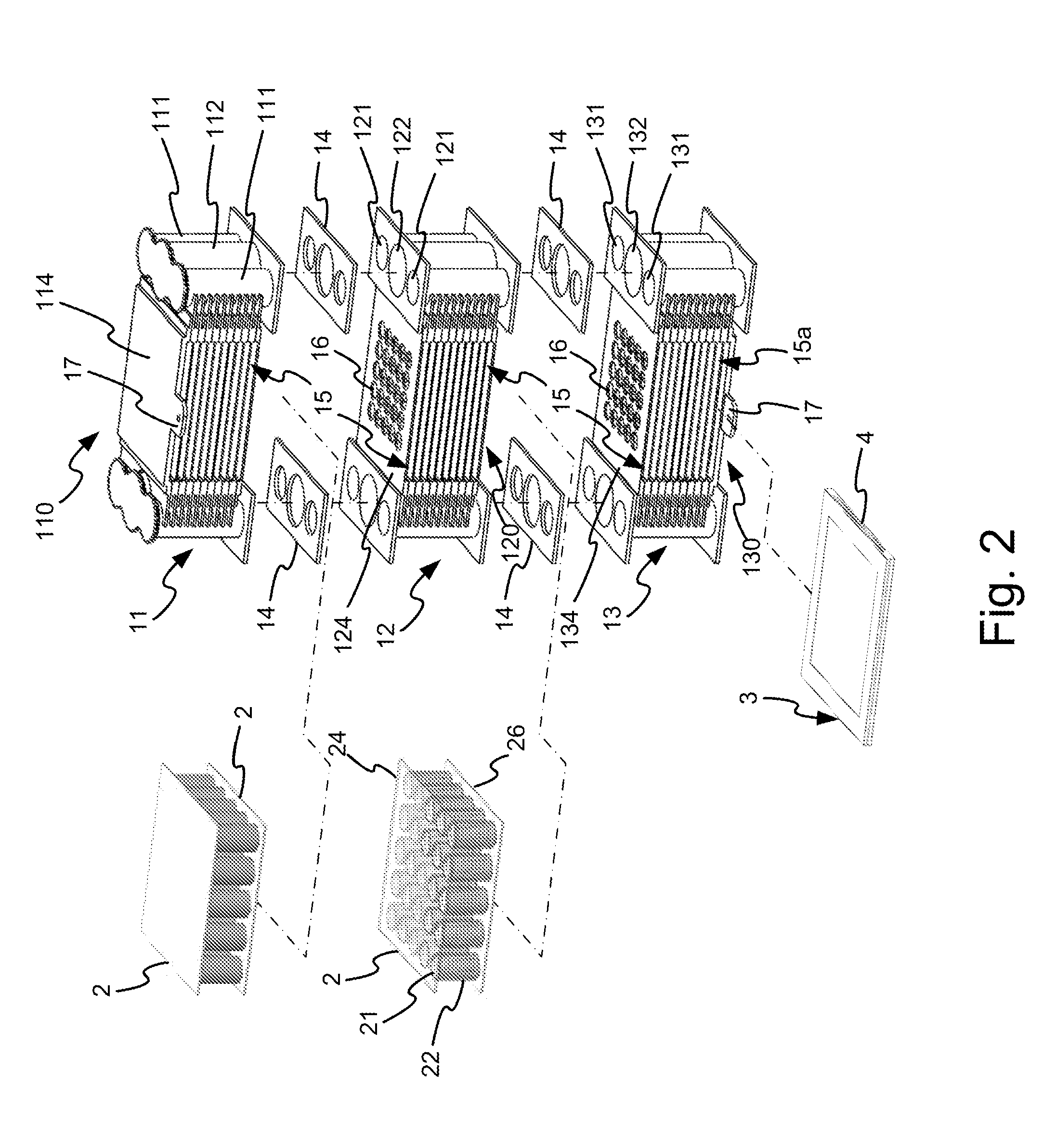
[0021]Referring to FIGS. 1 and 3, there is shown a planar SOFC stack according to the preferred embodiment of the present invention. The planar SOFC stack includes a supporting mechanism 1, two pressing and conducting units 2 and planar SOFC units 3. The supporting mechanism 1 includes three parts that are manufactured separately and connected to one another.

[0022]The first part of the supporting mechanism 1 includes a stacking unit 110 formed between two gas-distributing units 11. The gas-distributing units 11 may be made of metal or ceramics. Each of the gas-distributing units 11 includes two inlet pipes 111 and an outlet pipe 112. The axes of the pipes 111 and 112 extend vertically and parallel to one another.

[0023]The stacking unit 110 includes slots 15 defined therein and separated from one another by boards 114. The boards 114 extend horizontally. The uppermost board 114 includes a load-contacting tab 17 extending from a front edge thereof. The lowermost board 114 includes pos...


PUM

PropertyMeasurementUnit
conductiveaaaaaaaaaa
temperatureaaaaaaaaaa

Abstract

A solid oxide fuel cell (“SOFC”) stack device is disclosed. The SOFC stack includes SOFC units that can easily be stacked and electrically connected to one another. Furthermore, each of the SOFC units can easily be removed from the others and replaced with a new one. The fuel cell stack includes a supporting mechanism and two conducting and pressing units. The supporting mechanism includes three parts. Each part of the supporting mechanism includes slots defined therein for receiving the SOFC units. Each of the conducting and pressing units is located between two adjacent ones of the parts of the supporting mechanism.

Description

BACKGROUND OF INVENTION[0001]1. Field of Invention[0002]The present invention relates to a planar solid oxide fuel cell (“SOFC”) stack and, more particularly, to a planar SOFC stack including planar SOFC units that can easily be piled up and replaced with new ones.[0003]2. Related Prior Art[0004]To provide an adequate amount of electricity, several to tens of planar SOFC units are stacked and electrically connected to one another in serial. Thus, the planar SOFC units together form a planar SOFC stack. The planar SOFC units are secured to one another conventionally. Hence, the process for interconnecting the planar SOFC units is complicated. Furthermore, it is difficult to remove any of the planar SOFC units when it is out of order. Of course, it is difficult to replace the broken planar SOFC unit with a new one.[0005]The present invention is therefore intended to obviate or at least alleviate the problems encountered in prior art.SUMMARY OF INVENTION[0006]It is the primary objectiv...

Claims


Application Information

Patent Timeline
Patent Type & Authority Applications(United States)
IPC IPC(8): H01M8/24H01M8/04H01M50/77
CPCY02E60/50Y02E60/525H01M8/2425H01M2008/1293H01M8/2485H01M8/0232H01M8/0273H01M8/248H01M8/242H01M8/2432
Inventor LIN, HUNG-HSIANGLEE, RUEY-YICHENG, YUNG-NENG
Owner INST NUCLEAR ENERGY RES ROCAEC
Why Eureka
Try Eureka