Connector and connecting structure of flexible flat cable

a flexible flat cable and connector technology, applied in the field of manufacturing, can solve the problems of increasing product cost, increasing cost, waste of materials, etc., and achieve the effect of increasing the mounting reliability of the flexible flat cabl

Active Publication Date: 2012-04-26
TCL CHINA STAR OPTOELECTRONICS TECH CO LTD
View PDF3 Cites 0 Cited by
  • Summary
  • Abstract
  • Description
  • Claims
  • Application Information

AI Technical Summary

Benefits of technology

[0026]The advantage of the present invention is that: by disposing the groove on the main body, the cover plate is inserted into the groove for engaging with the flexible flat cable connected to the connector. The flexible flat cable is clipped by the cover plate and the boss for preventing the flexible flat cable from slipping outward, thereby preventing the flexible flat cable from releasing from the connector and increasing the mounting reliability of the flexible flat cable and the connector.

Problems solved by technology

Although this design solves the problem of releasing easily, there are three problems: Firstly, a mould is needed to manufacture the FFC with the two ear hooks, and the high manufacture precision for the FFC is needed, resulting in the increase of the cost.
Secondly, the ear hooks on the two sides of the FFC will increase the width of the FFC, so as to result in the waste of material and the increase of the product cost.
Thirdly, in use, the operator must assure that the ear hooks of the FFC have been engaged with the bosses, if fail to do this, the result is that the ear hooks of the FFC only loosely engage with the bosses, which will result in bad signal transmission, so as to influence the mounting reliability substantially.

Method used


Image

  • Connector and connecting structure of flexible flat cable
  • Connector and connecting structure of flexible flat cable
  • Connector and connecting structure of flexible flat cable

Examples


embodiment 1

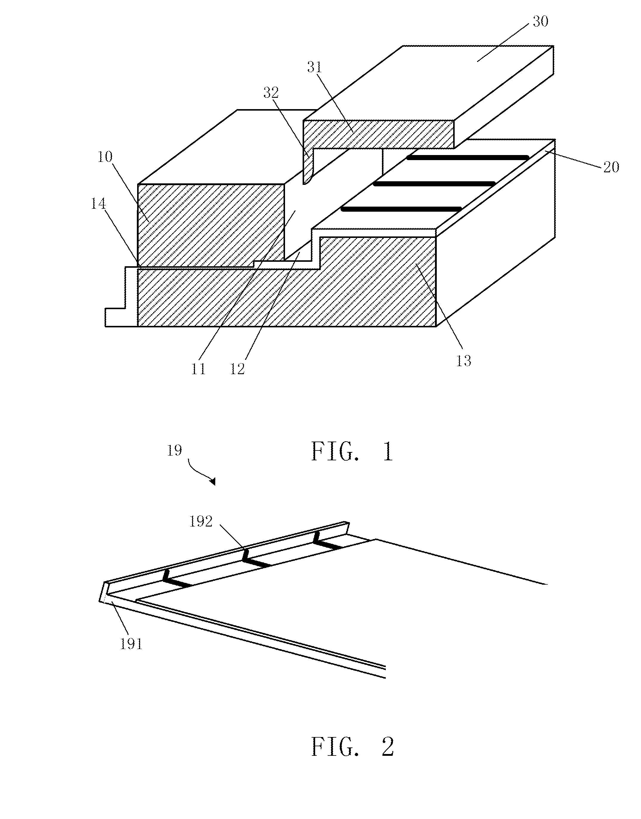
[0036]FIG. 1 shows a schematic view of an exploded structure of a connector in a first embodiment of the present invention. The connector comprises a main body 10, a plurality of electrical terminals 20 and a cover plate 30.

[0037]The main body 10 has a sidewall 11, a boss 13 and a groove 12 formed between the sidewall 11 and the boss 13. The height of the sidewall 11 is greater than that of the boss 13. The main body 10 further has a plurality of terminal grooves 14 passing through the sidewall 11 and being communicated with the groove 12.

[0038]The electrical terminal 20 is in a bent shape for resting on a top surface of the boss 13, a side of the groove 12 and a bottom surface of the groove 13, and for passing through the terminal groove 14 to extend out of the main body 10.

[0039]The cover plate 30 is L-shaped, having a cover portion 31 and an engaging portion 32 connected to the cover portion 31. As a preferred embodiment, the length of the engaging portion 32 should ensure that t...

embodiment 2

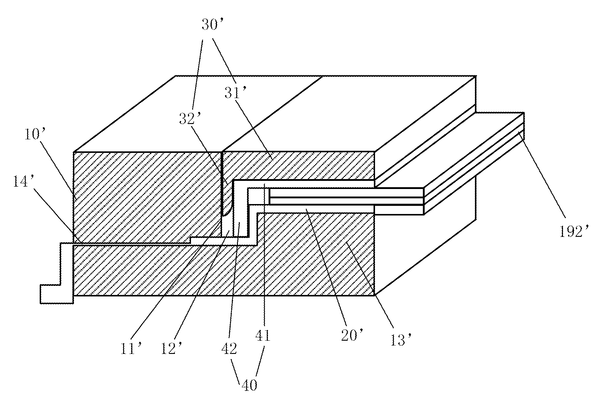
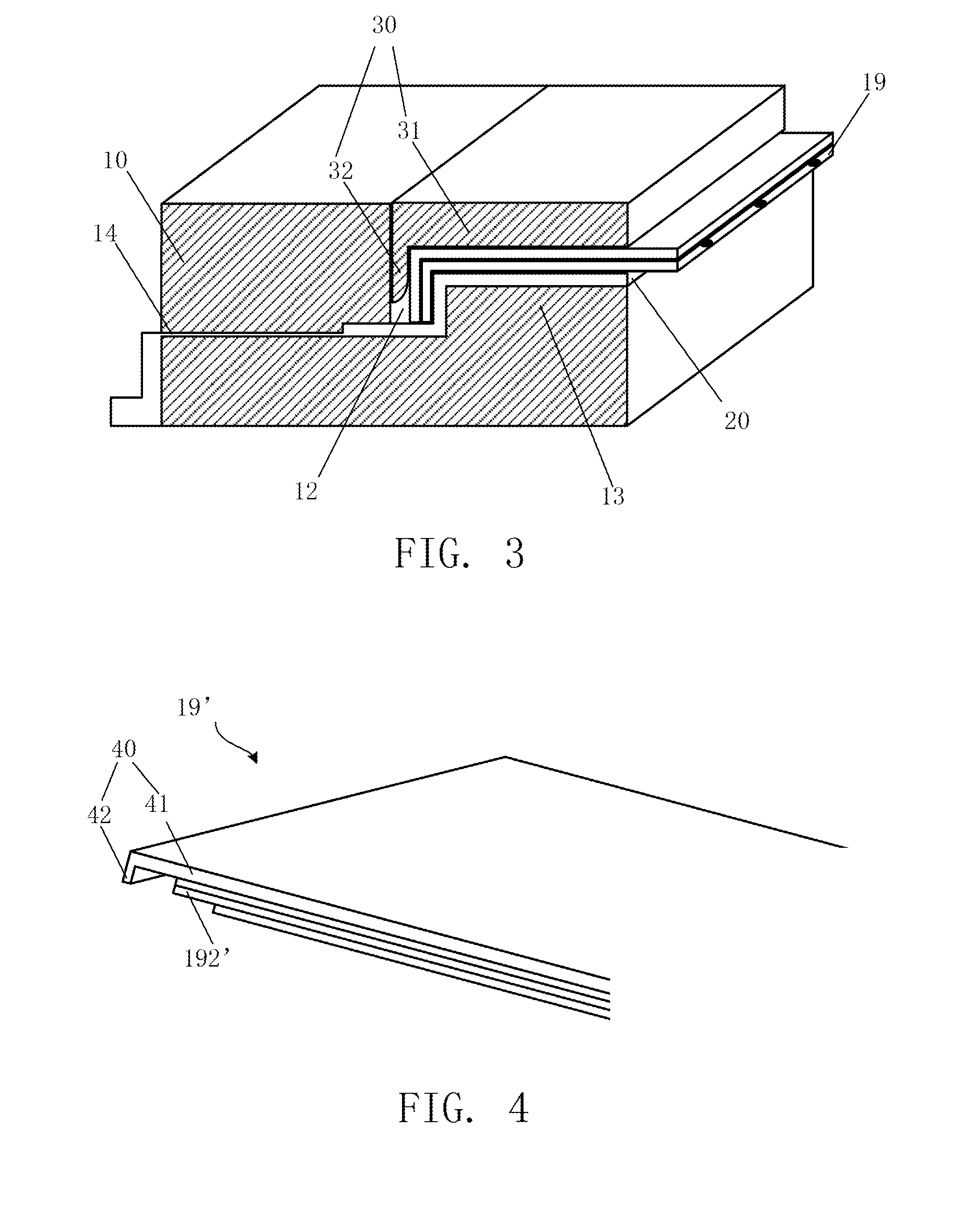
[0045]FIG. 4 is a schematic view of an exploded structure of a connecting structure of a flexible flat cable in a second embodiment of the present invention. In this embodiment, a composed structure of a connector is same as that of the connector of the first embodiment. In this embodiment, the connecting structure of the flexible flat cable has a difference from that of the first embodiment in that: the cable wires 192′ on one end of the flexible flat cable 19′ is exposed outside, the connecting structure of the flexible flat cable further has a reinforcing plate 40. The reinforcing plate 40 is L-shaped, having a covering portion 41 and a reinforcing portion 42 connected to the covering portion 41.

[0046]FIG. 5 is an assembly schematic view of the connecting structure of the flexible flat cable in the second embodiment of the present invention. Exposed ends of the cable wires 192′ of the flexible flat cable 19′ is engaged against a portion of the electrical terminal 20′ on the boss ...

embodiment 3

[0050]FIG. 6 is a schematic view of an exploded structure of a connecting structure of a flexible flat cable in a third embodiment of the present invention. In this embodiment, the flexible flat cable 19″ and the reinforcing plate 40″ is same as the structure of the flexible flat cable 19′ and the reinforcing plate 40 of the second embodiment. In this embodiment, the main body 10″ has a sidewall 11″ and a bottom wall 15. A middle portion of the bottom wall 15 protrudes upward to form a boss 13″, which is parallel to the sidewall 11″. A groove 12″ is defined between the boss 13″ and the sidewall 11″. A terminal groove 16 passes through the boss 13″. The electrical terminal 20″ is disposed on the bottom wall 15 of the main body 10″, one end of which passes through the terminal groove 14″ and extends out of the main body 10″, and the other end of which passes through the terminal groove 16.

[0051]FIG. 7 is an assembly schematic view of the connecting structure of the flexible flat cable...


PUM


Abstract

A connector and a connecting structure of a flexible flat cable are provided. The connector includes a main body, an electrical terminal and a cover plate. The main body has a sidewall and a boss. The sidewall and the boss define a groove therebetween. The electrical terminal is in a bent shape. One end of the electrical terminal is disposed on the boss. The cover plate has a cover portion and an engaging portion. The cover portion covers on the boss. The engaging portion is inserted into the groove of the main body. The electrical terminal is partially located between the boss and the cover plate. The present invention further provides the connecting structure of a flexible flat cable. The advantage of the present invention is that: by disposing the groove on the main body, the cover plate is inserted into the groove for engaging the flexible flat cable connected to the connector, thereby preventing the flexible flat cable from releasing from connector to increasing the mounting reliability.

Description

BACKGROUND OF THE INVENTION[0001]1. Field of the Invention[0002]The present invention relates to a manufacture field of a liquid crystal display, and more particularly to a connector and a connecting structure of a flexible flat cable.[0003]2. Description of the Prior Art[0004]Mass produced connector structures for connecting a flexible flat cable (FFC) are generally divided into two types: one of which is a common connector without special clamping design and this connector is easily released to result in the malfunction of the product in use; and the other one of which is that the FFC has two ear hooks on two sides thereof and the connector is designed with two bosses for engaging with the two ear hooks, respectively. Although this design solves the problem of releasing easily, there are three problems: Firstly, a mould is needed to manufacture the FFC with the two ear hooks, and the high manufacture precision for the FFC is needed, resulting in the increase of the cost. Secondly,...

Claims


Application Information

Patent Timeline
Patent Type & Authority Applications(United States)
IPC IPC(8): H01R12/77
CPCH01R12/77H01R13/639H01R13/447
Inventor HE, CHENGMINGZHANG, YANXUE
Owner TCL CHINA STAR OPTOELECTRONICS TECH CO LTD
Why Eureka
Try Eureka