System and method for deriving respiration from intracardiac electrograms (EGM) or ECG signals

a technology of intracardiac electrogram and ecg signal, which is applied in the field of implantable medical devices, can solve the problems of increasing device cost, size and complexity of implantation procedur

Active Publication Date: 2012-04-26
MEDTRONIC INC
View PDF6 Cites 11 Cited by
  • Summary
  • Abstract
  • Description
  • Claims
  • Application Information

AI Technical Summary

Problems solved by technology

Additional sensors and other hardware can increase device cost, size and implantation procedure complexity.

Method used


Image

  • System and method for deriving respiration from intracardiac electrograms (EGM) or ECG signals
  • System and method for deriving respiration from intracardiac electrograms (EGM) or ECG signals
  • System and method for deriving respiration from intracardiac electrograms (EGM) or ECG signals

Examples


Embodiment Construction

[0009]In the following description, references are made to illustrative embodiments. It is understood that other embodiments may be utilized without departing from the scope of the disclosure. In some instances, for purposes of clarity, identical reference numbers may be used in the drawings to identify similar elements. As used herein, the term “module” refers to an application specific integrated circuit (ASIC), an electronic circuit, a processor (shared, dedicated, or group) and memory that execute one or more software or firmware programs, a combinational logic circuit, or other suitable components that provide the described functionality.

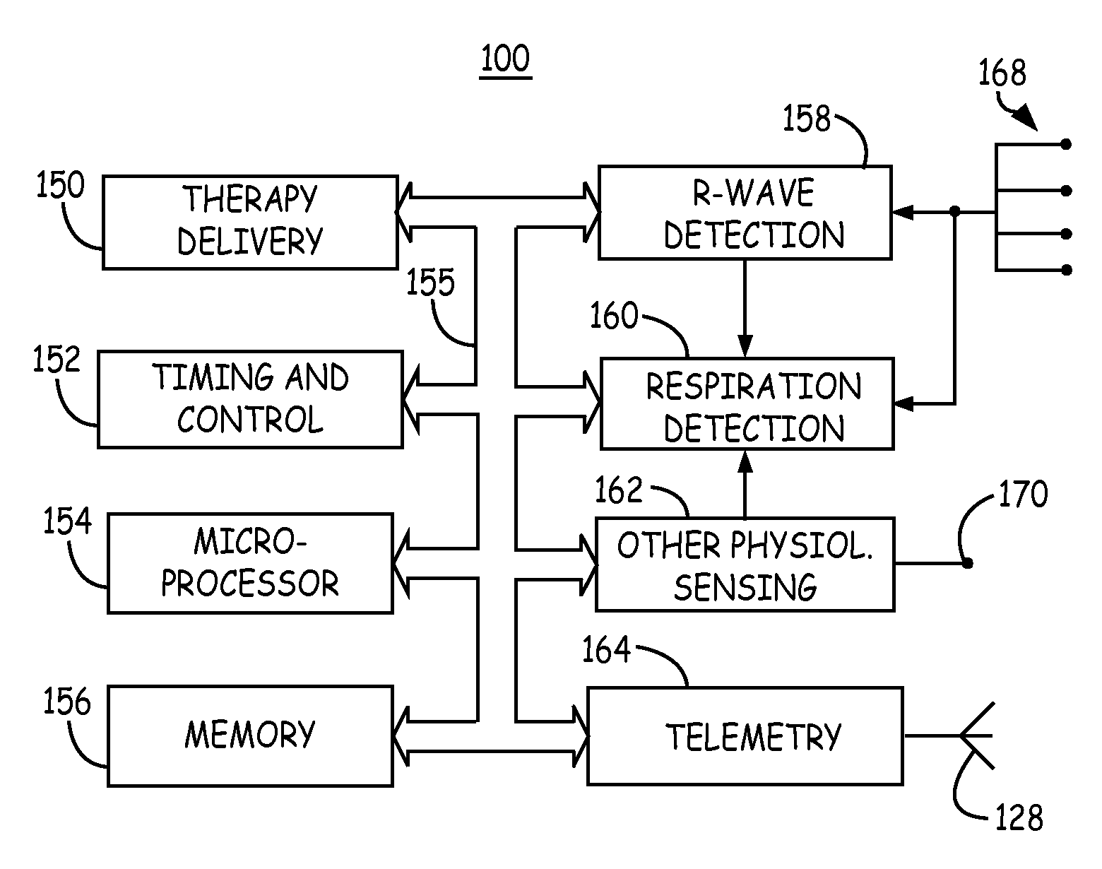
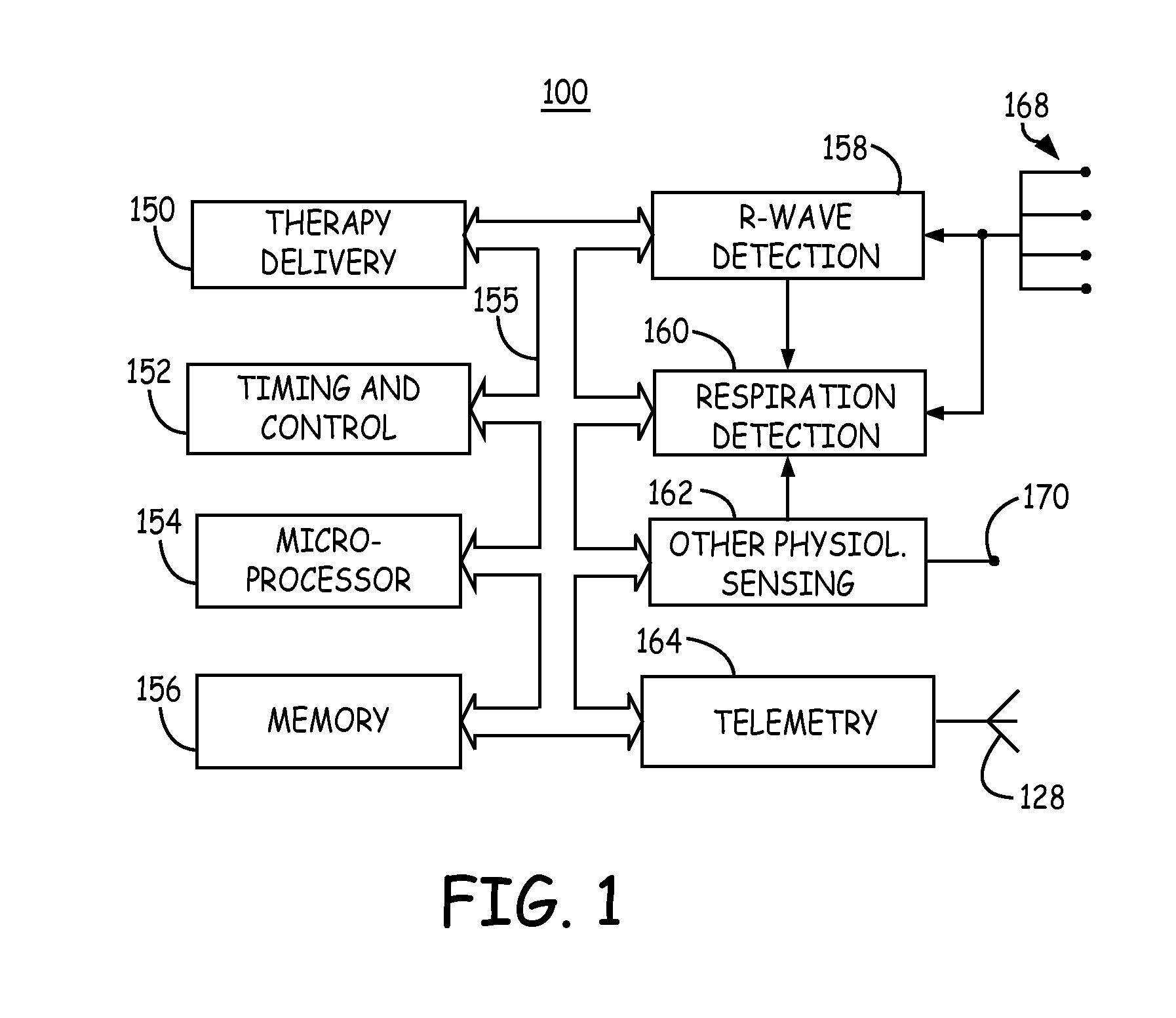
[0010]FIG. 1 is a functional block diagram of an IMD for monitoring a patient's respiration using a cardiac electrical signal. IMD 100 generally includes timing and control circuitry 152 and an operating system that may employ microprocessor 154 or a digital state machine for timing sensing and therapy delivery functions in accordance with a pr...


PUM


Abstract

A method and apparatus for monitoring respiration in a patient sense a cardiac electrical signal and detect signal peaks from the cardiac electrical signal. A peak amplitude waveform is generated from the signal peaks. a first derivative of the peak amplitude waveform is computed. Inspiration pulses are derived from the first derivative signal, and a respiration metric can be computed using the inspiration pulses derived from the cardiac electrical signal.

Description

TECHNICAL FIELD[0001]This disclosure relates generally to implantable medical devices and, in particular, to a method and apparatus for monitoring respiration in a patient using a cardiac electrical signal.BACKGROUND[0002]Implantable pacemakers, cardiovertor defibrillators (ICDs), and hemodynamic monitors, are examples of implantable medical devices (IMDs) that sense cardiac electrical signals for monitoring a patient's heart rhythm. The cardiac electrical signals are sensed using electrodes positioned in or around the heart. Such electrodes may be transvenous or intracardiac electrodes for sensing EGM signals or placed subcutaneously to sense ECG signals.[0003]Sometimes additional information relating to other physiological signals is desired for monitoring a patient. For example, information relating to the patients blood pressure, respiration, blood oxygen saturation, or patient activity may be desired. Typically, additional sensors and leads are required in order to sense additi...

Claims


Application Information

Patent Timeline
Patent Type & Authority Applications(United States)
IPC IPC(8): A61B5/0205
CPCA61B5/0452A61B5/0816A61B5/7278A61B5/7239A61B5/7282A61B5/349
Inventor ZHANG, XUSHENGGILLBERG, JEFFREY M.
Owner MEDTRONIC INC
Why Eureka
Try Eureka