Method and apparatus for suppressing vibration

a vibration suppressing and apparatus technology, applied in the field vibration suppressing apparatuses, can solve the problems of disadvantageous selection of vibration suppressing methods which are not as effective as the other methods, and the difficulty of the worker to determine, so as to prevent the vibration suppressing control

Active Publication Date: 2012-04-26
OKUMA CORP
View PDF5 Cites 29 Cited by
  • Summary
  • Abstract
  • Description
  • Claims
  • Application Information

AI Technical Summary

Benefits of technology

[0023]According to the present invention, effectiveness is determined for the control for changing the rotation speed of the rotary shaft to the stable rotation speed and / or the control for fluctuating the rotation speed based on the variation parameters including a reference rotation speed that is input or previously set, amplitude and period, and thereafter, an effective control is performed or an ineffective control is not continuously adopted. It is therefore possible to prevent the vibration suppression control that is ineffective against suppression of the chatter vibration from being continuously adopted.
[0024]Further, providing the display device makes it possible to reliably inform the worker of an occurrence of chatter vibration, so as to urge the worker to take countermeasures such as changing the depth of cut, or to reset the variation parameters.

Problems solved by technology

For this reason, when regenerative type chatter vibration generates during the actual processing, it is difficult for the worker to determine whether the current rotation speed of the rotary shaft falls in the high speed region or in the low speed region, and consequently, the worker may disadvantageously select a vibration suppressing method which is not as effective as the other method.

Method used


Image

  • Method and apparatus for suppressing vibration
  • Method and apparatus for suppressing vibration
  • Method and apparatus for suppressing vibration

Examples


first embodiment

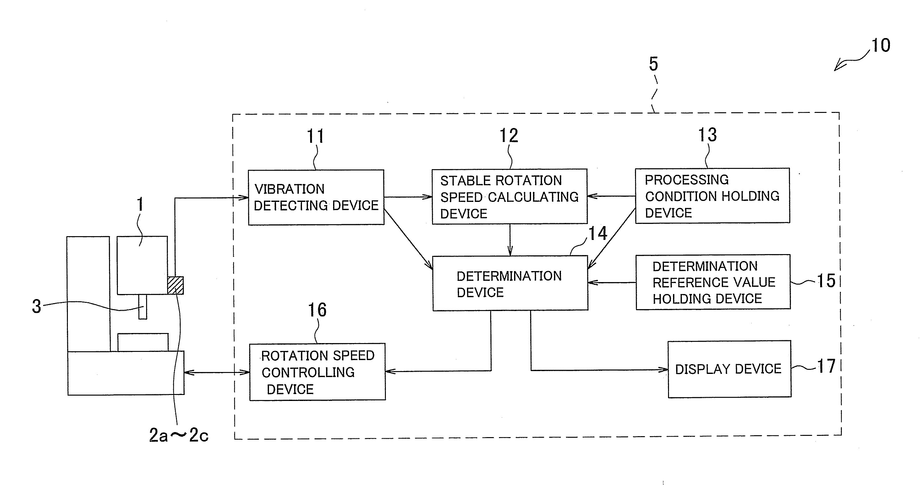
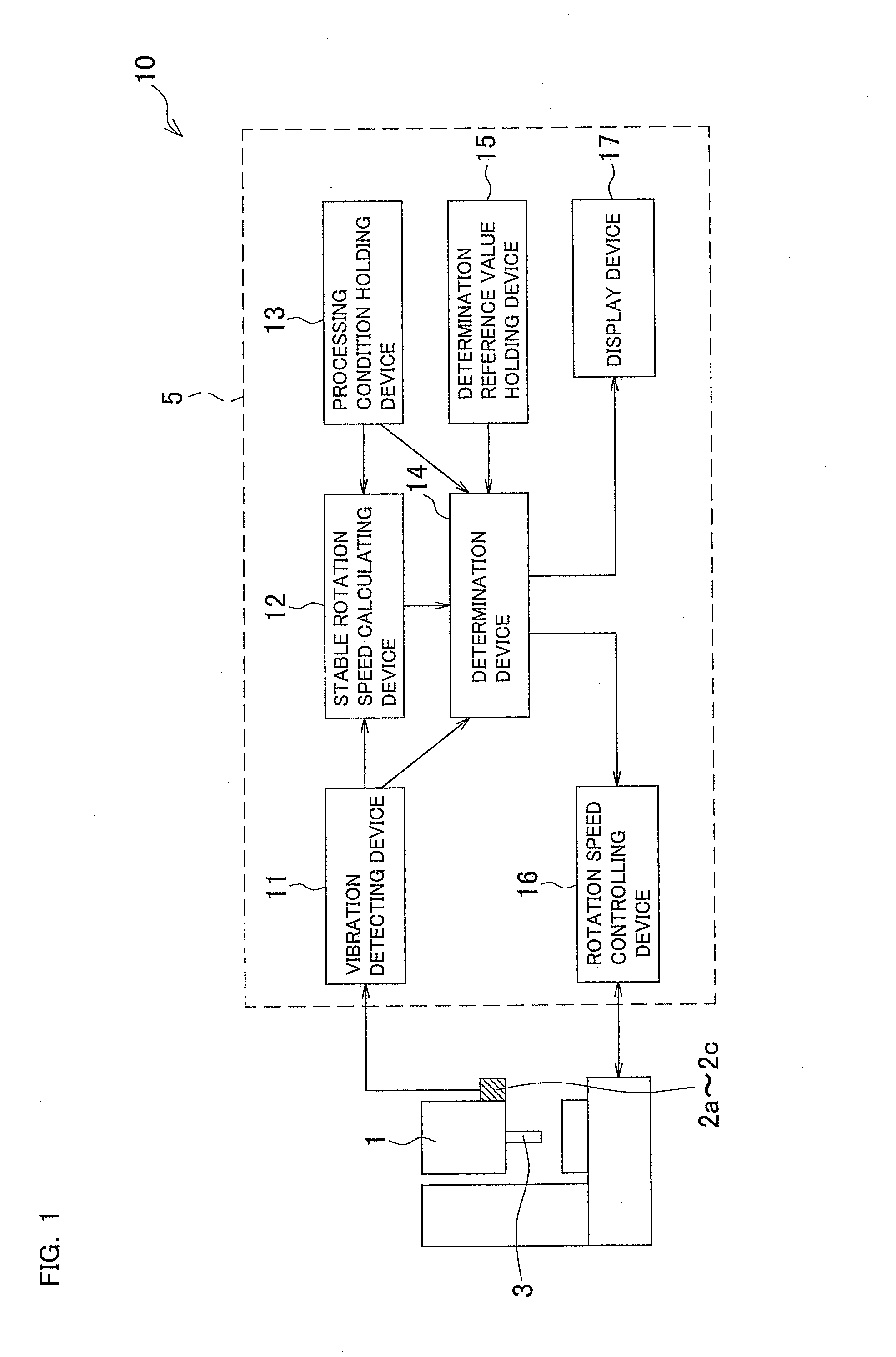
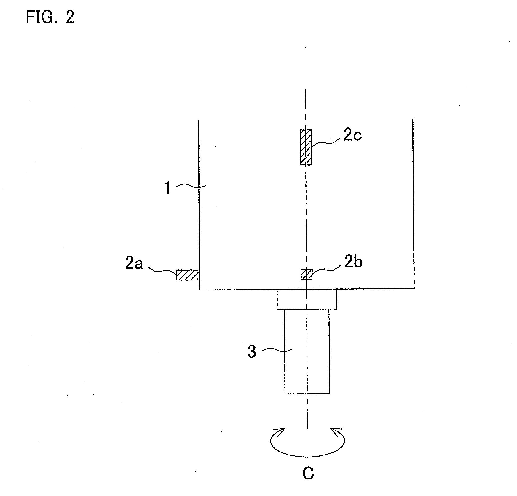
[0034]FIG. 1 is an explanatory diagram illustrating a block configuration of a vibration suppressing apparatus 10 according to a first embodiment of the present invention. FIG. 2 is an explanatory view laterally illustrating a rotary shaft housing 1, which is subject to vibration suppression. FIG. 3 is an explanatory view illustrating the rotary shaft housing 1 in a shaft direction.

[0035]A vibration suppressing apparatus 10 is configured to suppress “chatter vibration” generated in a rotary shaft 3 which is rotatably provided around a C-axis of the rotary shaft housing 1. The vibration suppressing apparatus 10 includes vibration sensors 2a-2c for detecting time-domain vibrational accelerations (which means vibrational accelerations on a time axis) which are characteristic values derived from vibration generated at the rotating rotary shaft 3, and a controller 5 for analyzing the detection values of the vibration sensors 2a-2c to determine whether or not “chatter vibration” has occur...

second embodiment

[0053]FIG. 7 is a block diagram of a vibration suppressing apparatus according to a second embodiment of the present invention. Parts similar to those previously described in the first embodiment are denoted by the same reference numerals, and detailed description thereof will be omitted.

[0054]A vibration suppressing apparatus 20 is configured to suppress “chatter vibration” generated in a rotary shaft 3 which is rotatably provided around a C-axis of the rotary shaft housing 1. The vibration suppressing apparatus 20 includes vibration sensors 2a-2c for detecting time-domain vibrational accelerations (which means vibrational accelerations on a time axis) generated at the rotating rotary shaft 3, and a controller 21 for analyzing the detection values of the vibration sensors 2a-2c to determine whether or not “chatter vibration” has occurred and based on the determination result controlling rotation speed of the rotary shaft 3. As with the first embodiment, the vibration sensors 2a-2c ...


PUM


Abstract

A vibration suppressing method and a vibration suppressing device are disclosed. After detection of chatter vibration using at least one vibration detecting device, a stable rotation speed for suppressing the chatter vibration is calculated using a stable rotation speed calculating device. A determination device then compares a detection value detected by the vibration detecting device, a predetermined setting value, and/or a current value that is calculated based on at least one of the detection value and the setting value, to a predetermined determination reference value that is previously set. Thereafter, the determination device determines whether or not the stable rotation speed is adopted in accordance with the comparison result, and changes rotation speed of the rotary shaft to the stable rotation speed if the stable rotation speed is adopted.

Description

BACKGROUND OF THE INVENTION[0001]This application claims the entire benefit of Japanese Patent Application Number 2010-238893 filed on Oct. 25, 2010, the entirety of which is incorporated by reference.TECHNICAL FIELD[0002]The present invention relates to a vibration suppressing method and a vibration suppressing apparatus for a machine tool which is provided with a rotary shaft for rotating a tool or a workpiece to process the workpiece, and more particularly to a vibration suppressing method and a vibration suppressing apparatus for suppressing chatter vibration generated during processing of the workpiece.BACKGROUND ART[0003]Conventionally, as a vibration suppressing method for a machine tool provided with a rotary shaft for rotating a tool or a workpiece to process the workpiece, a method disclosed in Japanese Laid-open Patent Application Publication No. 2003-340627 is known. According to this vibration suppressing method, in order to suppress regenerative type chatter vibration ...

Claims


Application Information

Patent Timeline
Patent Type & Authority Applications(United States)
IPC IPC(8): G05B19/404
CPCB23Q17/0976G05B19/404G05B2219/41256G05B2219/41115G05B2219/37435
Inventor UENO, HIROSHI
Owner OKUMA CORP
Why Eureka
Try Eureka