Microgrid Control System

a micro-grid and control system technology, applied in the field of power grids, can solve the problems of over-complex existing micro-grid control systems, often requiring power for macro-grids, and negatively affecting the environmen

Active Publication Date: 2012-04-26
THE BOEING CO
View PDF23 Cites 90 Cited by
  • Summary
  • Abstract
  • Description
  • Claims
  • Application Information

AI Technical Summary

Problems solved by technology

However, macrogrids frequently require power to be transmitted across long distances.
These facilities may negatively impact

Method used


Image

  • Microgrid Control System
  • Microgrid Control System
  • Microgrid Control System

Examples


Embodiment Construction

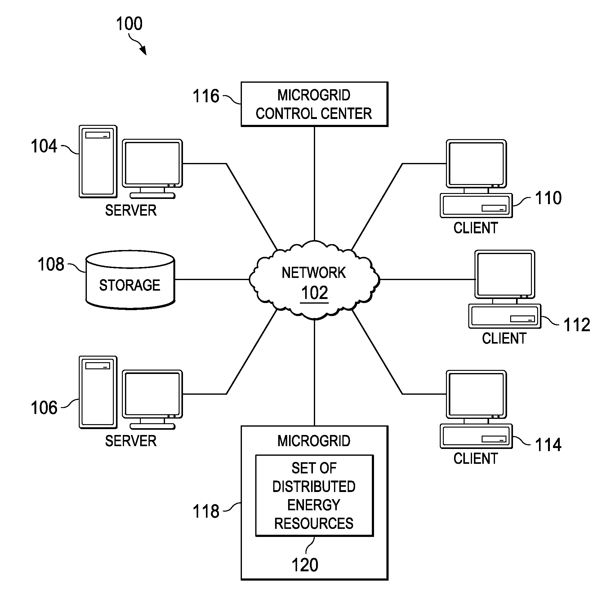
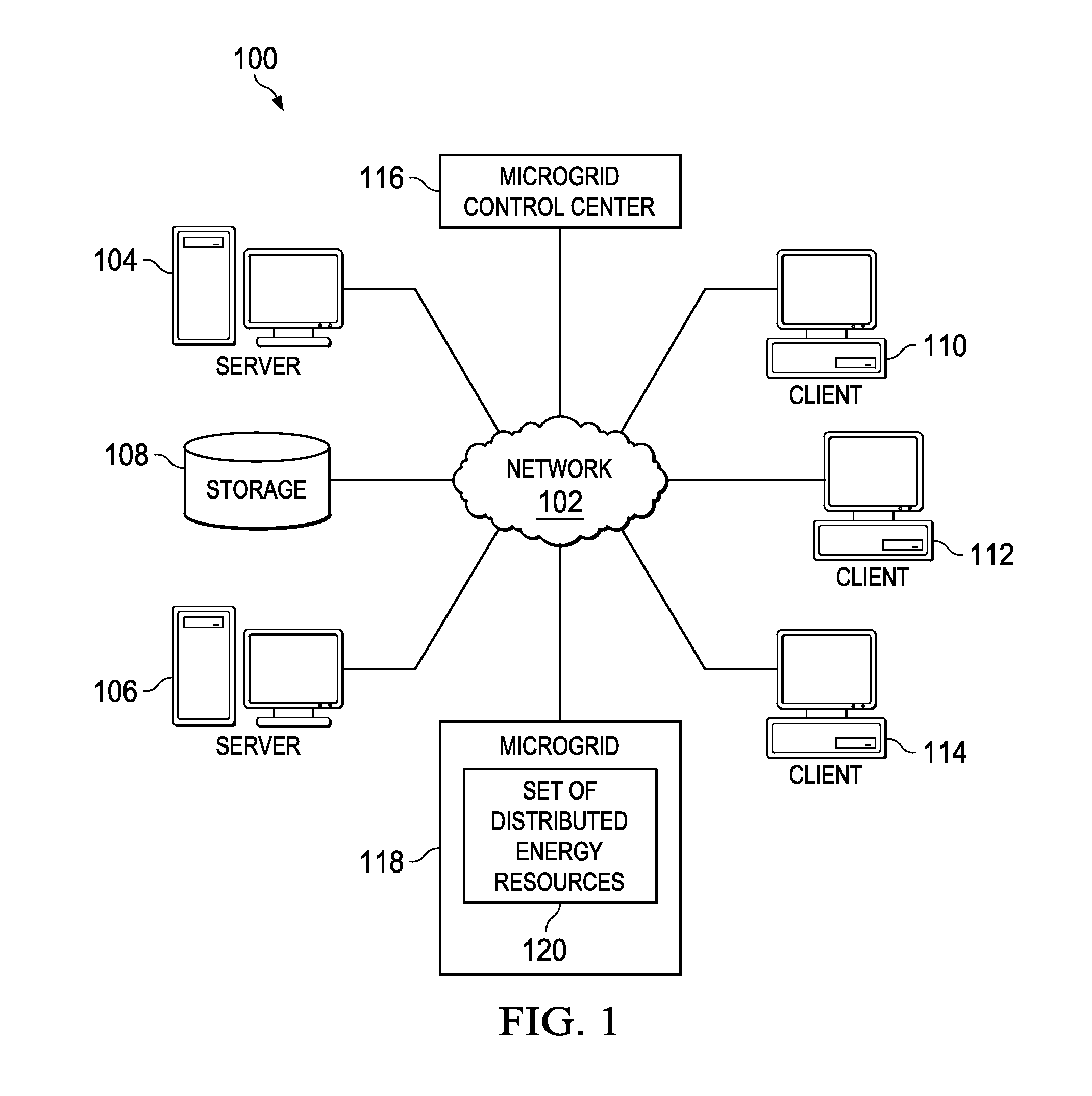
[0019]With reference now to the figures and in particular with reference to FIG. 1, an illustrative diagram of a data processing environment for a microgrid control system is provided in which illustrative embodiments may be implemented. It should be appreciated that FIGS. 1-5 are only provided as illustrations of data processing environments for the depicted implementations in FIGS. 1-5 and are not intended to imply any limitations with regard to the environments in which different embodiments may be implemented. Many modifications to the depicted environments may be made.

[0020]FIG. 1 depicts a pictorial representation of a network of data processing systems in which advantageous embodiments may be implemented. Network data processing system 100 is a network of computers in which the advantageous embodiments may be implemented. Network data processing system 100 contains network 102, which is the medium used to provide communications links between various devices and computers conn...


PUM


Abstract

A method, apparatus, and computer program product is provided for configuring a microgrid. A first configuration of the microgrid having a set of microgrid elements is initialized. An address for each element in the set of microgrid elements of the microgrid is verified. In response to receiving status data from the set of microgrid elements connected in a peer-to-peer network indicating a reconfiguration of the microgrid, the set of microgrid elements is re-aligned to form a second grid configuration. The second grid configuration is executed.

Description

BACKGROUND INFORMATION[0001]1. Field[0002]The present disclosure relates generally to power grids and, in particular, to a method, apparatus, and computer program product for managing microgrids. Still more particularly, the present disclosure relates to a method, apparatus, and computer program product for an adaptable microgrid robust control system.[0003]2. Background[0004]Currently, most electric power is generated by macrogrids. Macrogrids typically are large, centralized power plants, such as nuclear power plants, hydroelectric plants, and fossil fuel powered plants. Macrogrids commonly have good economies of scale. However, macrogrids frequently require power to be transmitted across long distances. These large facilities frequently generate power using non-renewable sources of energy, such as coal or gas. These facilities may negatively impact the environment.[0005]A microgrid is a localized grouping of electric power generation sources and loads. A microgrid may also be ref...

Claims


Application Information

Patent Timeline
IPC IPC(8): G06F1/26G06F15/173
CPCG06F1/26Y04S40/164H04L67/12H04L41/12Y04S40/18Y04S40/00H02J3/00H02J3/38H04L69/00H04L65/40G05B15/02
Inventor CARRALERO, MICHAEL A.QUIAMBAO, JIMMY M.POUNDS, DALE KENNETH
Owner THE BOEING CO
Why Eureka
Try Eureka