
Automatic feeding and crimping device of applicator in terminal making machine for flexible printed circuits, flat cables and cable terminals

a technology of flexible printed circuits and terminal making machines, which is applied in the direction of metal working apparatuses, fixed connections, manufacturing tools, etc., can solve the problems of low yield, difficult to ensure, complicated operation, and difficult to secure the preciseness of the end produ

Active Publication Date: 2012-05-03
TIEN CHENG JEN
View PDF2 Cites 4 Cited by
  • Summary
  • Abstract
  • Description
  • Claims
  • Application Information

AI Technical Summary

Benefits of technology

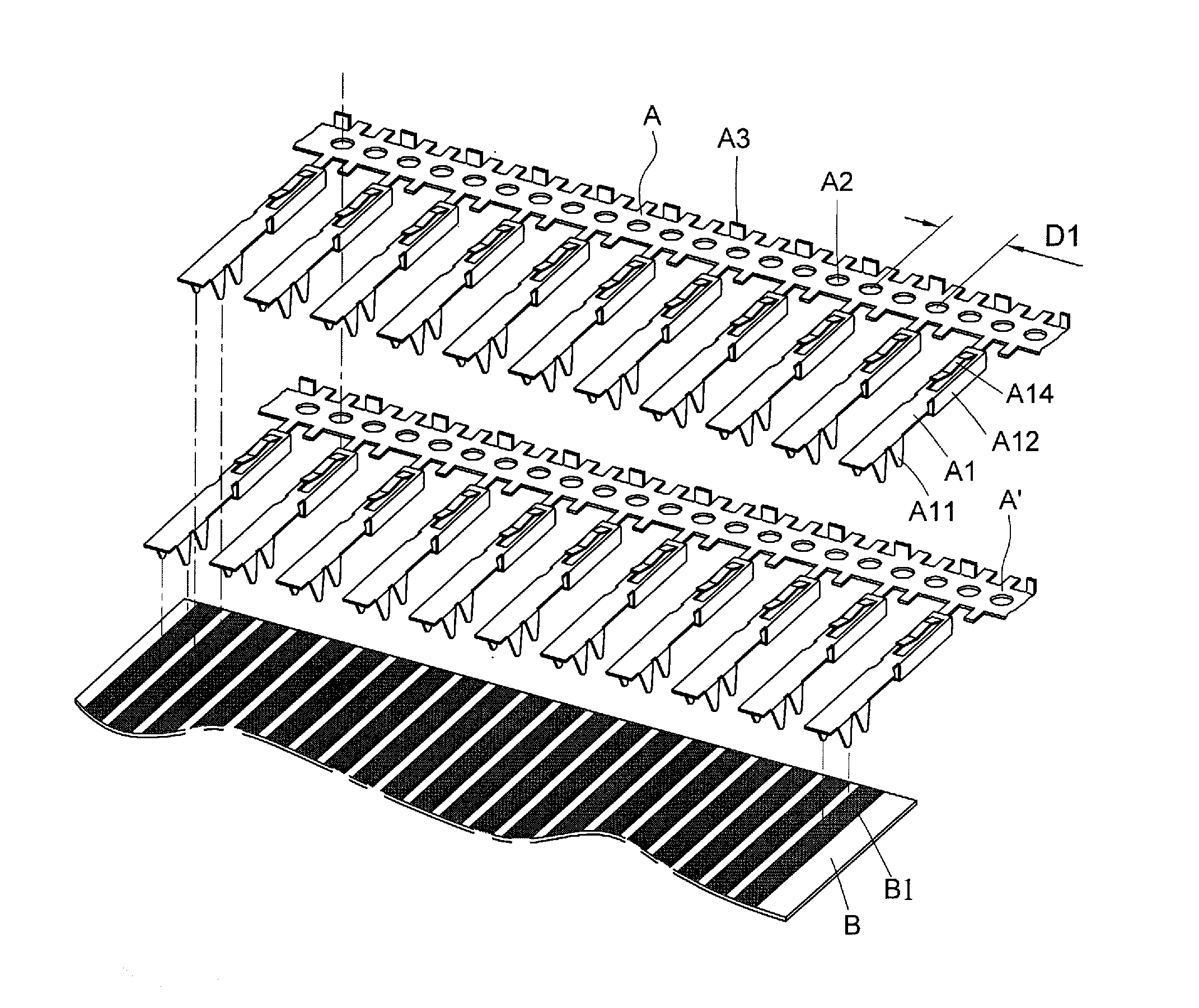
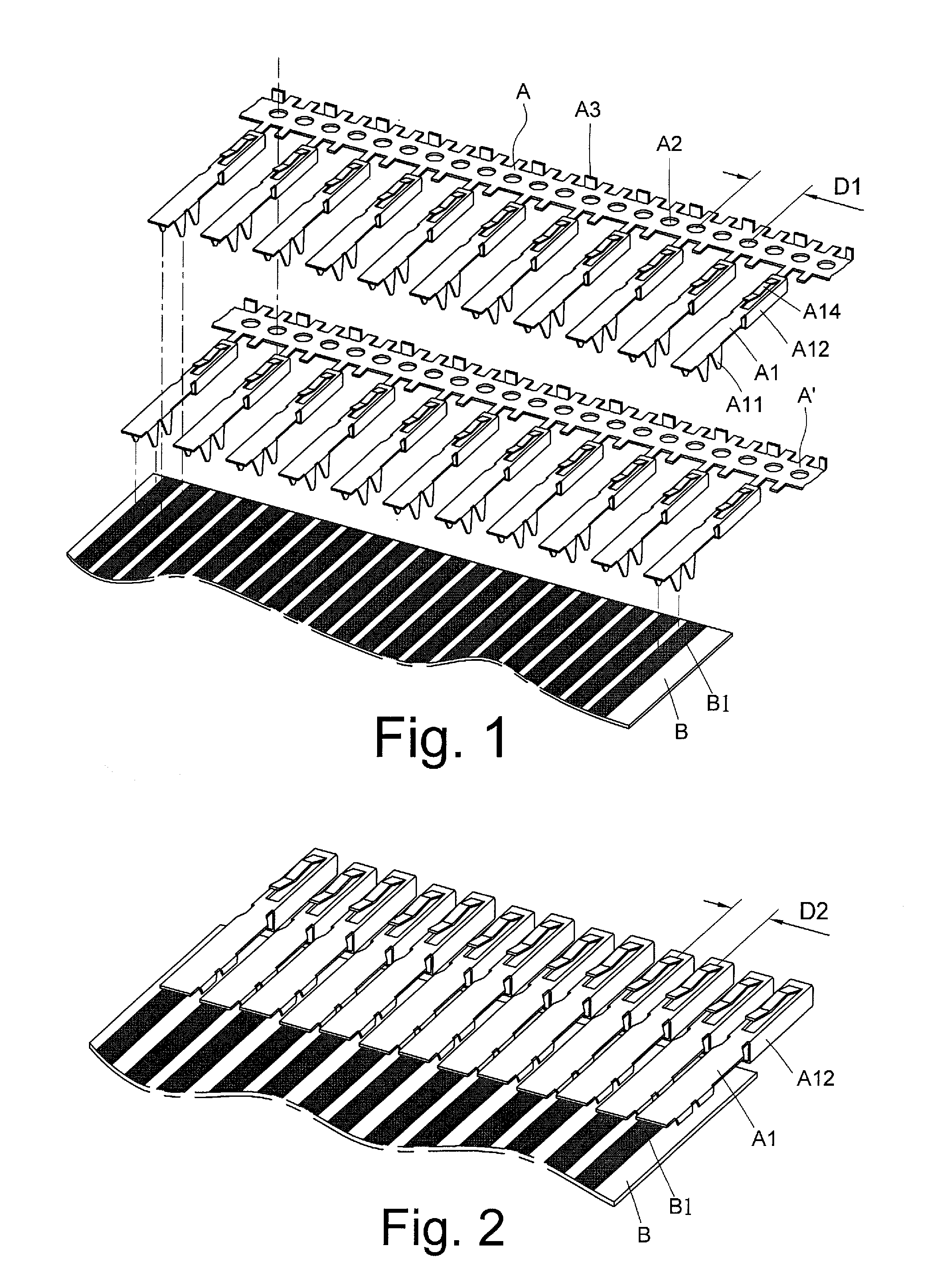
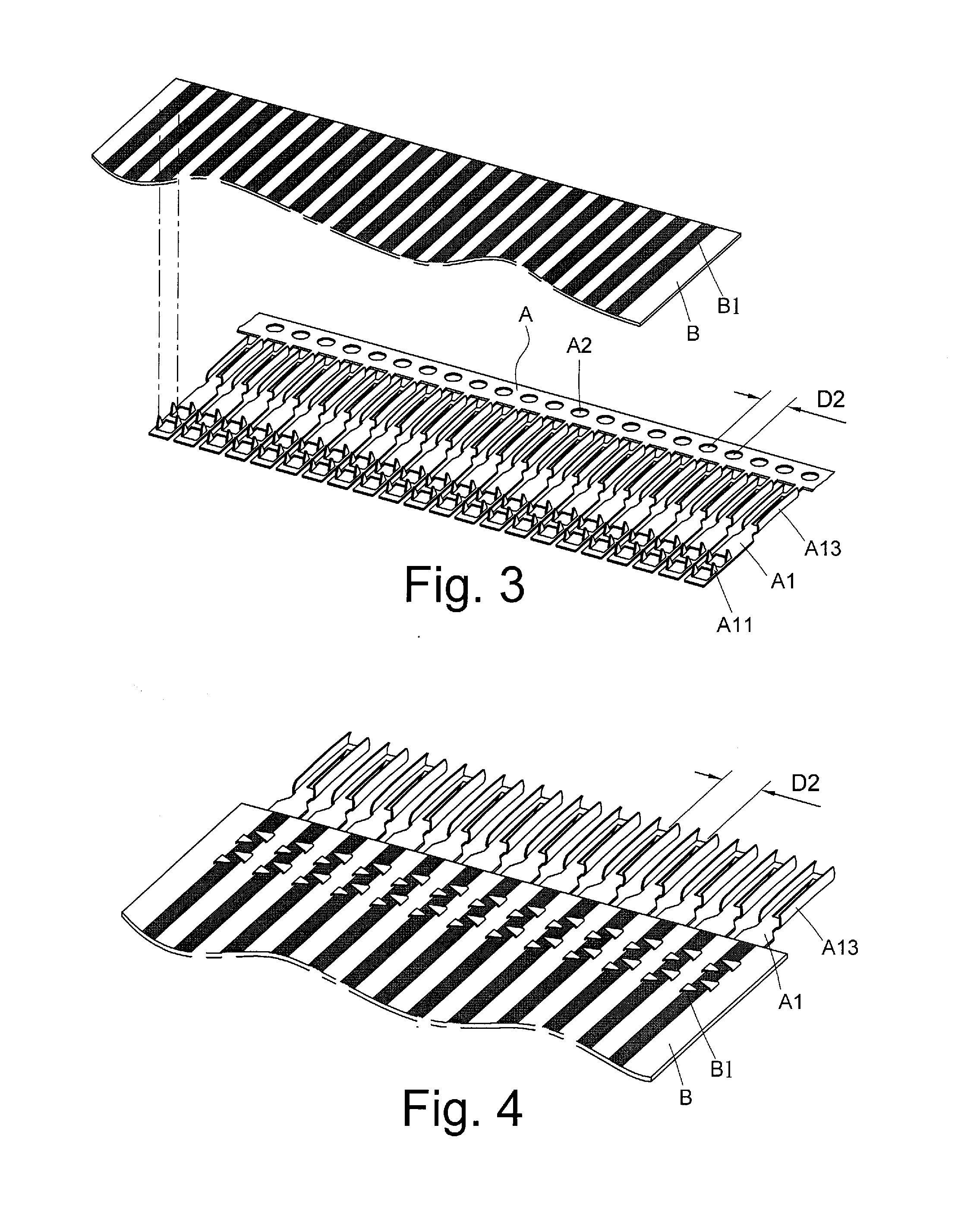
[0012]The inventor of the present invention, basing on his decades of experience in terminal crimping, molding, and manufacturing, conducted long-term researches, and eventually developed an “automatic feeding and crimping device of an applicator in a terminal making machine for flexible printed circuits, flat cables and cable terminals.” Therein, to perform a crimping process for continuous terminal bands A with square-headed contacting sections A12, two said continuous terminal band A and A′ with terminals A spaced by 5.08 mm are offset stacked and placed in a feeding channel, so as to make two adjacent terminals A1 on respective said bands A and A′ spaced by 2.54 mm, equal to the default distance of a copper-foil / copper-wire connecting end B1 of a flexible printed circuit / flexible flat cable B (for an application of 1.27 mm, terminal bands with terminals spaced by 2.54 mm are stacked offset in the same manner), and thus the abreast terminals A1 in a number between two and forty can be perfectly crimped with the copper-foil / copper-wire connecting end B1 in a single step, thereby providing advantageous of fast process, low defective rate and zero accumulated feeding error. To perform a crimping process for a continuous terminal band A with U-headed contacting sections A13 spaced by the default distance of the copper-foil / copper-wire connecting end B1, i.e. 2.54 mm, the continuous terminal band A is placed into the feeding channel, and the abreast terminals A1 in a number as desired, between two and forty, can be crimped with the copper-foil / copper-wire connecting end B1 in a single step of the flexible printed circuit / flexible flat cable B. To make products with terminals spaced by 1.27 mm, terminal bands with terminal spaced by 2.54 mm may be offset stacked the abreast terminals A1 in a number as desired, between two and forty, can be crimped with the copper-foil / copper-wire connecting end B1 in a single step of the flexible printed circuit / flexible flat cable B, so that perfect connection can be achieved in a fast, neat, low-loss and error-free manner.
[0014]The disclosed device further has a band retaining hook, so that the terminals A1 of the set number being fed forward can be prevent from going back or bias. Moreover, the disclosed device is ended by a scrap chopper, which serves to chop scrap equidistantly into small pieces, for facilitating disposal and collection of the scrap.

Problems solved by technology

However, it is difficult to ensure the precise combination between the copper-foil / copper-wire connecting end B1 of the flexible printed circuit / flexible flat cable B and the terminals A1 through the crimping process.
In such a case, the biggest concerns are the feeding accumulated error evolving through the 13-pin crimping process and high material loss (and in turn the low yield) due to jams and / or deviation of the terminals or the flexible printed circuit / flexible flat cable B. In addition, the operation is complicated and preciseness is difficult to secure.
Thus, even for crimping terminals of the same specification, several procedures with use of different jigs / molds have to be done, and consequently incur high processing costs, unstable product quality as well as very high defective rate.

Method used


Image

  • Automatic feeding and crimping device of applicator in terminal making machine for flexible printed circuits, flat cables and cable terminals
  • Automatic feeding and crimping device of applicator in terminal making machine for flexible printed circuits, flat cables and cable terminals
  • Automatic feeding and crimping device of applicator in terminal making machine for flexible printed circuits, flat cables and cable terminals

Examples


Embodiment Construction

[0025]Referring to FIG. 5 through FIG. 8, the present invention provides an automatic feeding and crimping device equipped at a lower portion of a conventional terminal making machine P. The disclosed device has a base 1, a vertical sliding guide 11 fixed on a side of the base 1, a slider 12 settled in the vertical sliding guide 11 to be vertically movable and connected to a main shaft of the terminal making machine P, an upper crimping mold part 121 and upper cutter 122 fixed to a bottom of the slider 12, wherein the upper crimping mold part 121 has a downward surface provided with a plurality of spacing pins 1211, a lower mold part 123 deposited on the base 1 upward corresponding to the upper crimping mold part 121, wherein the lower mold part 123 has an upward face provided with a plurality of bend-guiding recesses 1231 for guiding piercing legs A11 to bend, and a cutter receiving surface 1221 deposited on the base 1 upward corresponding to the cutter 122.

[0026]As shown in FIG. 7...


PUM

PropertyMeasurementUnit
Currentaaaaaaaaaa
Digital informationaaaaaaaaaa
Flexibilityaaaaaaaaaa

Abstract

An automatic feeding and crimping device of an applicator in a terminal making machine for flexible printed circuits, flat cables and cable terminals allows easy adjustment of a feed number of terminals and serves to automatically feed the terminals for the applicator to crimp the terminals with a flexible printed circuit, a flat cable or other cable terminals, thereby providing industrial benefits related to fast and precise terminal processing and flexible feed pitches.

Description

BACKGROUND OF THE INVENTION[0001]1. Technical Field[0002]The present invention relates to an innovate design of a feeding system of an applicator in a terminal making machine, which serves to automatically feed flexible printed circuits, flexible flat cables and so on for crimping terminals thereon.[0003]2. Description of Related Art[0004]A terminal crimping machine is known to combine metal terminals with stranded wire or a copper cord covered by the metal terminals in a mold so as to establish electric connection between electrode ends or signal ends of the terminals and the wire or cord.[0005]Presently, flexible printed circuits and flexible flat cables have been widely used in electrical machinery, electronic and computer-related fields for electrodes or signal transmission. The so-called flexible printed circuit (also known as FPC) is made by coating copper foil on a flexible polyimide (PI) or polyethylene terephthalate (PET) substrate, and etching the copper foil to create a s...

Claims


Application Information

Patent Timeline
IPC IPC(8): H01R43/055
CPCH01R12/69H01R43/055Y10T29/5327Y10T29/53226Y10T29/53235
Inventor TIEN, CHENG JEN
Owner TIEN CHENG JEN
Learn More