Pneumatic tire
a technology of pneumatic tires and pneumatic cylinders, applied in the field of pneumatic tires, can solve problems such as uneven wear, and achieve the effect of easy indication of wear sta
- Summary
- Abstract
- Description
- Claims
- Application Information
AI Technical Summary
Benefits of technology
Problems solved by technology
Method used
Image

Examples
first embodiment
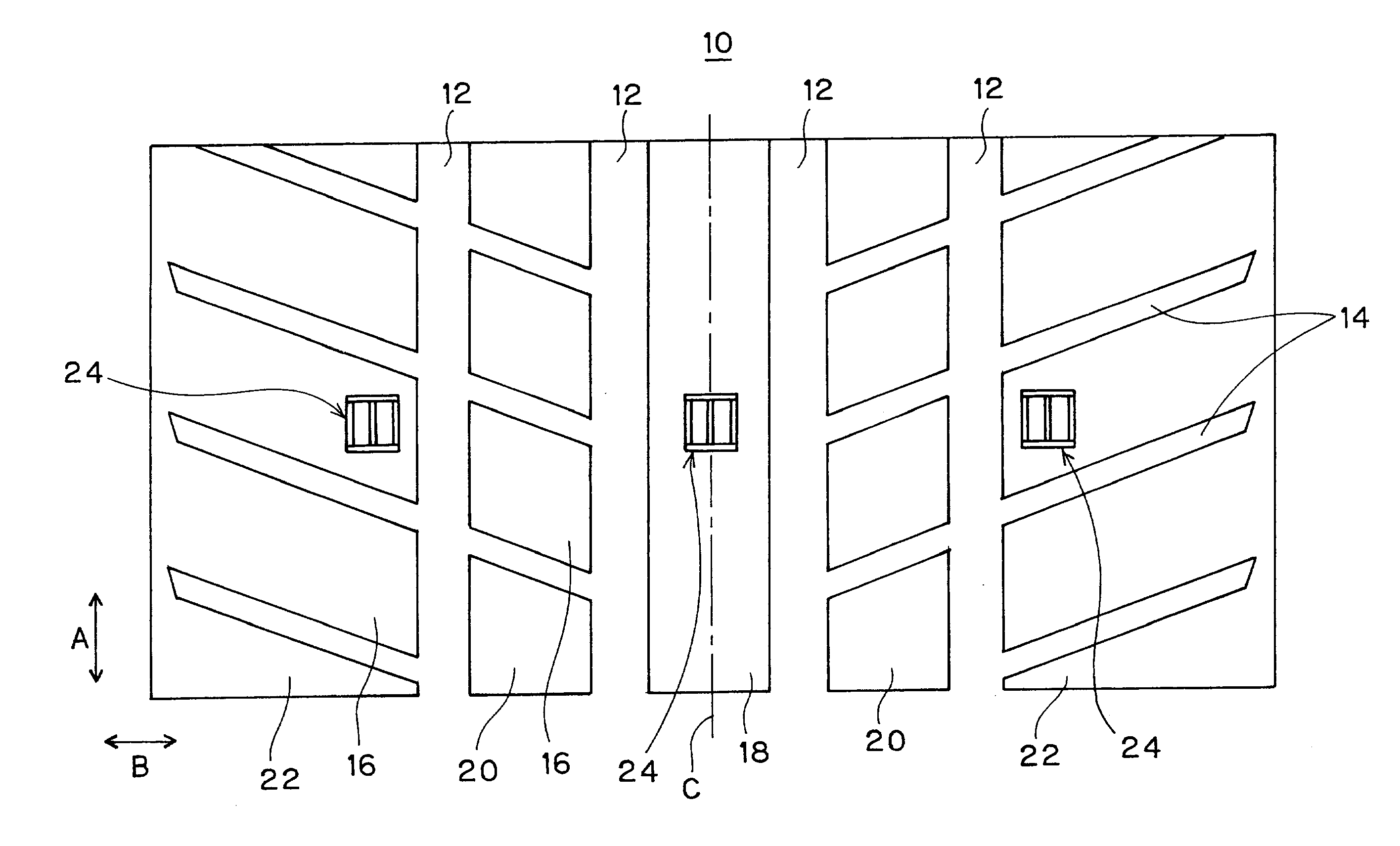
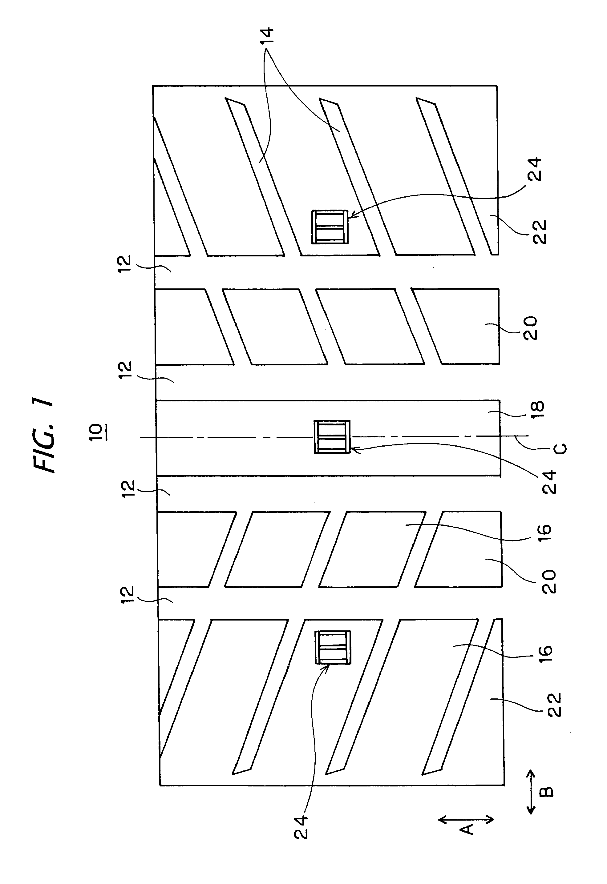
[0023]The pneumatic tire according to a first embodiment, although not shown, comprises a pair of right and left beads, a pair of right and left side wall parts, and a tread part 10 provided between both side wall parts so as to connect outer ends in a radial direction of the right and left side wall parts with each other. The tire has a carcass extending across a pair of the bead parts. The carcass comprises at least one carcass ply, which passes the side wall part from the tread part 10, the both ends of which being locked by a ring-shaped bead core, and reinforces the above each part. The bead core is embedded in the bead part. A belt comprising at least two layers of a rubber-coated steel cord layer is provided at an outer peripheral side of the carcass in the tread part 10, and the belt reinforces the tread part 10 at the outer periphery of the carcass.
[0024]A plurality of circumferential grooves (main grooves) 12 extending in a tire circumferential direction A in a straight sh...
second embodiment
[0046]FIGS. 7A to 7C show the indication constitution at each wear stage of the wear indicator 24 according to a second embodiment. As shown in the drawings, in this example, the wear indicator 24 indicates “9” in a first wear stage (initial stage of wear), “6” in a second wear stage (intermediate stage of wear) and “3” in a third wear stage (end stage of wear).
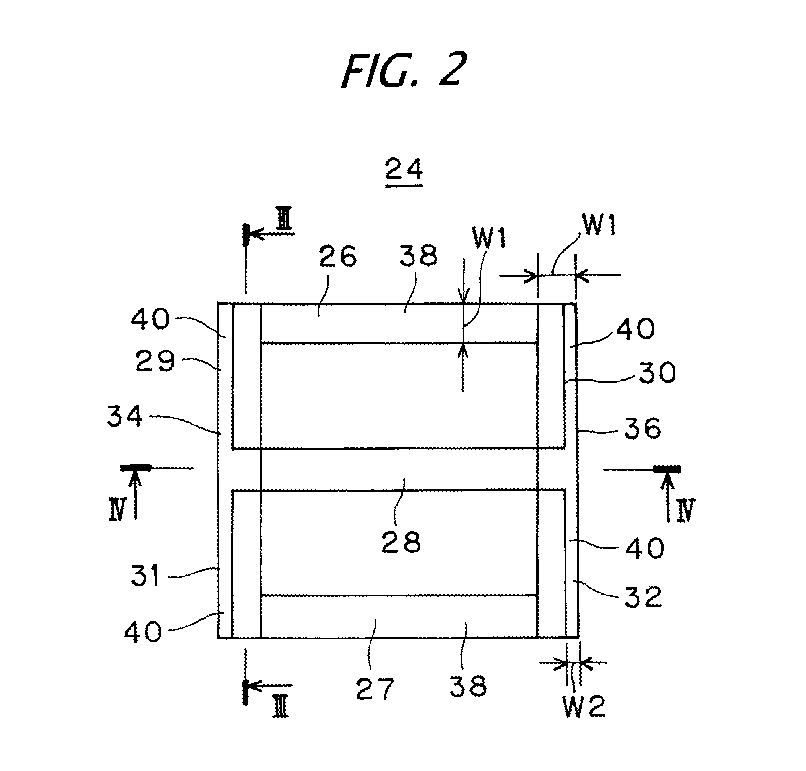
[0047]To make the indication possible, in this example, three sipes of the uppermost sipe 26, the lowermost sipe 27 and the intermediate sipe 28, extending in the lateral direction each are formed into the indication part 38 having the first groove width W1 over the entire depth direction H of the sipe. The lower-right sipe 32 is also formed into the indication part 38 having the first groove width W1 over the entire depth direction H of the sipe.
[0048]On the other hand, the upper-right sipe 30 is formed into the indication part 38 having the first groove width W1 up to the depth of the first wear stage from the tread surface...
third embodiment
[0053]FIGS. 8A to 8D show the indication constitution at each wear stage of the wear indicator 24 according to a third embodiment. As shown in the drawings, in this example, the wear indicator 24 has four wear stages in the depth direction H of the sipe, and indicates “0” in a first wear stage which is an initial stage of wear, “7” in a second wear stage, “4” in a third wear stage and “1” in a fourth wear stage which is the end stage of wear.
[0054]To make the indication possible, in this example, the right side longitudinal sipe 36 comprising the upper-right sipe 30 and the lower-right sipe 32 is formed into the indication part 38 having the first groove width W1 over the entire depth direction H of the sipe. The uppermost sipe 26 is formed into the indication part 38 having the first groove width W1 up to the depth of the first wear stage and the second wear stage, terminates there, and disappears in and after the third wear stage. The lowermost sipe 27 is formed into the indicatio...
PUM
 Abstract
Description
Claims
Application Information
 - R&D Engineer
- R&D Manager
- IP Professional
- Industry Leading Data Capabilities
- Powerful AI technology
- Patent DNA Extraction
Browse by: Latest US Patents, China's latest patents, Technical Efficacy Thesaurus, Application Domain, Technology Topic.
© 2024 PatSnap. All rights reserved.Legal|Privacy policy|Modern Slavery Act Transparency Statement|Sitemap