Coupling member, fluid-device connecting jig, and fluid-device connecting structure

a technology of fluid-device connecting jigs and coupling parts, which is applied in the direction of bends, manufacturing tools, siphons, etc., can solve the problems of reducing sealing strength, creeping deformation of connection parts, and reducing sealing strength, so as to achieve good workability and facilitate the effect of performan

Active Publication Date: 2018-06-07
CKD
View PDF0 Cites 20 Cited by
  • Summary
  • Abstract
  • Description
  • Claims
  • Application Information

AI Technical Summary

Benefits of technology

[0017]According to the coupling member configured as above, the following advantageous effects can be achieved. Specifically, the first coupling segment has a U-like having an opening at one side. The first coupling segment is engaged with the second coupling segment so as to circumferentially surround the first connection part and the second connection part over a range more than 180 degrees of their entire circumference. No engagement portion is provided outside the coupling member in its radial direction. Thus, the coupling member itself is compact in size. Accordingly, the coupling member can be mounted in even such an insufficient space because many fluid devices are located in parallel and thus pipes or wall surfaces are close to each other. This can achieve good workability.
[0018]Another aspect of the present disclosure provides a fluid-device connecting jig to be used in the aforementioned coupling member, wherein the first coupling segment is provided, on its outer peripheral surface, with a second jig-catching part, the second coupling segment is provided, on its outer peripheral surface, with a first jig-catching part, and the fluid-device connecting jig includes a common hooking part engageable with the first jig-catching part, and a first-lock-position hooking part and a second-lock-position hooking part each engageable with the second jig-catching part. Accordingly, the first coupling segment and the second coupling segment can be placed in a connection state changeable between the first lock position and the second lock position.
[0019]Further, another aspect of the present disclosure provides a fluid-device connecting jig to be used in the aforementioned coupling member, wherein the fluid-device connecting jig is inserted from same direction as a direction of mounting the coupling member onto the first connection part and the second connection part to engage the first coupling segment and the second coupling segment. This configuration enables a one-way work, which can be easily performed with good workability even in a narrow space where many fluid devices are installed in parallel.
[0020]Still further, another aspect of the present disclosure provides a fluid-device connecting jig to be used in the aforementioned coupling member, wherein when the fluid-device connecting jig remains attached to the coupling member, the fluid-device connecting jig indicates a retightened state of the coupling member. Accordingly, the retightened state of the coupling member can be easily ascertained from its appearance. This enables an operator to find and address a fluid device with the coupling member in a retightened state at a glance during maintenance with good workability.
[0021]Another aspect of the present disclosure provides the fluid-device connecting structure including the aforementioned coupling member.

Problems solved by technology

Thus, for example, if the connection parts are exposed alternately to abnormally high temperature chemical liquid and abnormally low temperature pure water for a long term, the connection parts may be creep-deformed, leading to decreased sealing strength.
Such a decreased sealing strength may cause leakage of liquid.

Method used


Image

  • Coupling member, fluid-device connecting jig, and fluid-device connecting structure
  • Coupling member, fluid-device connecting jig, and fluid-device connecting structure
  • Coupling member, fluid-device connecting jig, and fluid-device connecting structure

Examples


Embodiment Construction

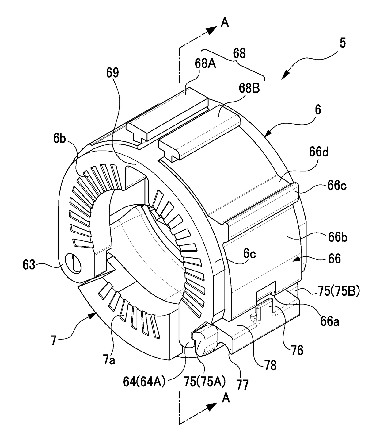
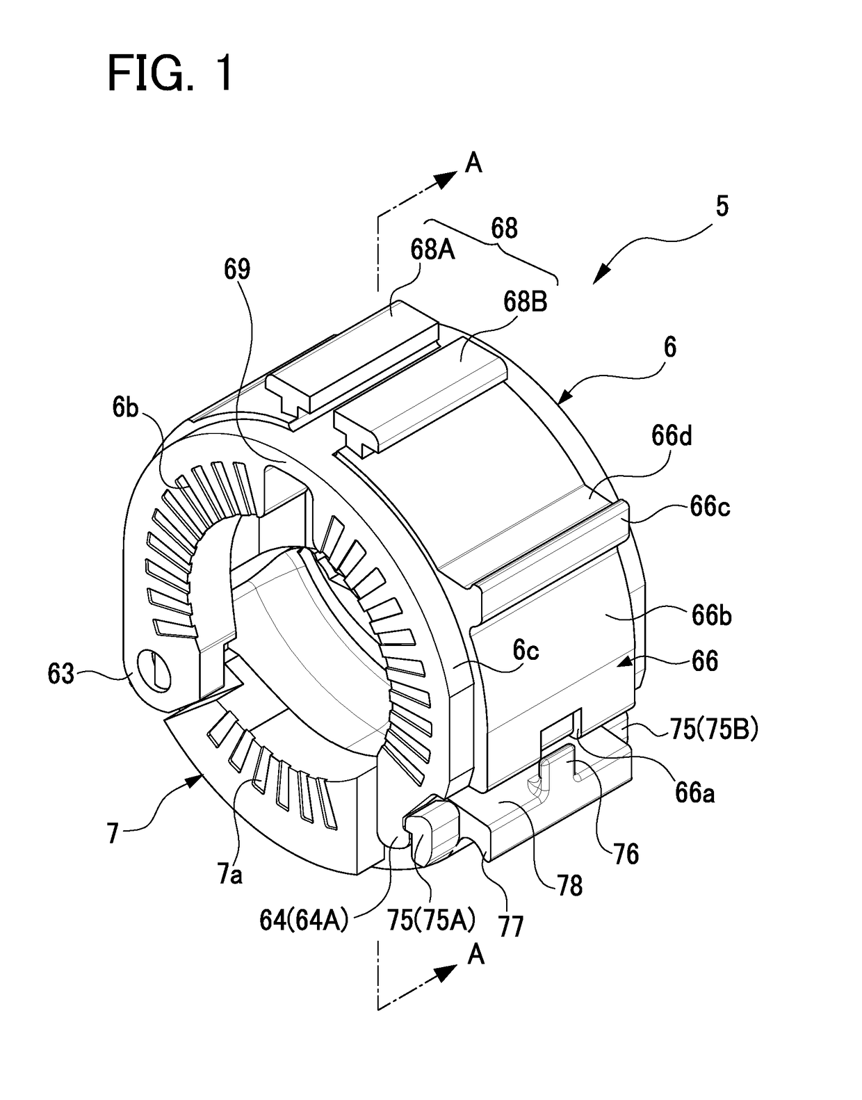
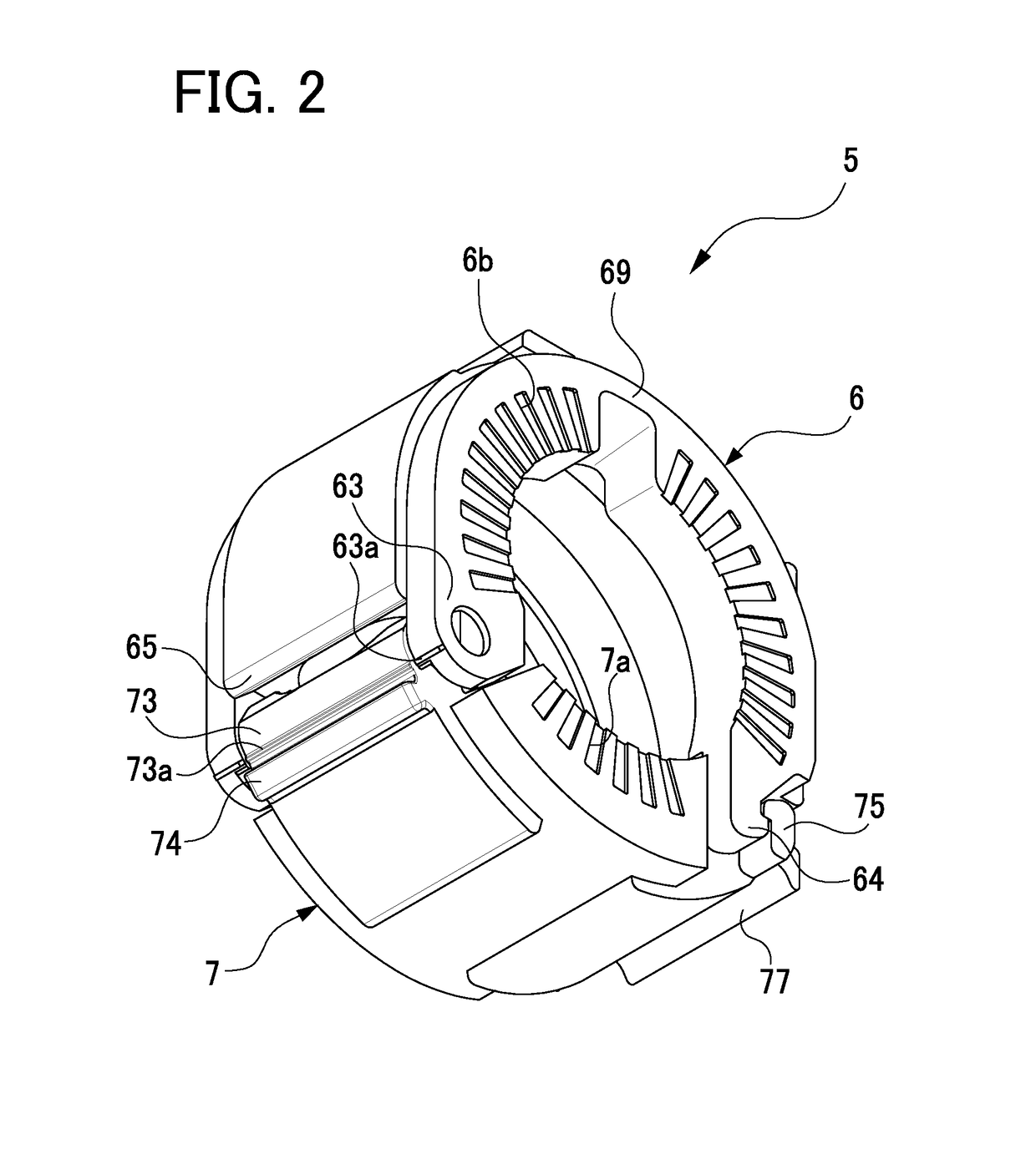
[0065]A detailed description of an embodiment of a coupling member, a fluid-device connecting jig, and a fluid-device connecting structure which are ones of typical embodiments of this disclosure will now be given referring to the accompanying drawings. The fluid-device connecting structure 1 will be first described in detail below. FIGS. 1 to 4 are perspective views showing a coupling member 5 in a first lock position seen from different angles. FIG. 5 is a perspective view of the coupling member 5 before engagement. FIG. 6 is a cross-sectional view taken along a line A-A in FIG. 1. FIG. 7 is a cross-sectional view taken along a line B-B in FIG. 5. FIG. 8 shows a relationship between the coupling member 5 and a first fluid device 2. FIG. 9 is a front view of the coupling member 5 in the process of being mounted onto one of fluid devices placed in parallel.

[0066]FIG. 12 illustrates how to connect fluid devices 2 and 3 with the coupling member 5, (a) showing an exploded view of the f...


PUM

PropertyMeasurementUnit
cylindrical outer shapeaaaaaaaaaa
circumferenceaaaaaaaaaa
diameteraaaaaaaaaa

Abstract

A fluid-device connecting structure includes a first fluid device having a first connection part, a second fluid device having a second connection part, an annular seal member to connect the first and second connection parts, and a coupling member to keep the first and second connection parts in a connected state. The coupling member includes a first coupling segment and a second coupling segment, each including at one end a first hinge part or a second hinge part. The first and second connection parts each have a cylindrical outer shape. The first coupling segment has a U-like shape having an opening and surrounds the first and second connection parts over a range more than 180 degrees of an entire circumference of each of the first and second connection parts.

Description

CROSS-REFERENCE TO RELATED APPLICATIONS[0001]This application is based upon and claims the benefit of priority from the prior Japanese Patent Applications No. 2016-233961 filed on Dec. 1, 2016 and No. 2017-211516 filed on Nov. 1, 2017, the entire contents of which are incorporated herein by reference.BACKGROUNDTechnical Field[0002]This disclosure relates to a coupling member to be used in a fluid-device connecting structure including a first fluid device having a first connection part, a second fluid device having a second connection part, an annular seal member for connecting the first connection part and the second connection part, and a coupling member for maintaining the first and second connection parts in a connected state.Related Art[0003]For control of chemical liquid or solution to be used in a semiconductor manufacturing process, a liquid crystal producing process, or another process, there have conventionally been used various kinds of fluid devices: for example, valves s...

Claims


Application Information

Patent Timeline
Patent Type & Authority Applications(United States)
IPC IPC(8): F16L3/10F16L43/02F16L23/16F16L21/06F16L23/032F16L47/14F16L23/06
CPCF16L3/1075F16L43/02F16L23/162F16L21/06F16L23/032F16L47/145F16L23/06B25B27/10B25B27/16F16L21/08F16L3/1233F16L23/167F16L23/04F16L23/003F16L23/22
Inventor TAKEDA, HIDEYUKIIWATA, HIROKIYASUE, HIROTONISHIMURA, YASUNORI
Owner CKD
Why Eureka
Try Eureka