Foam dispensing device

a technology of foam and dispensing device, which is applied in the direction of liquid transferring device, dispenser, single-unit apparatus, etc., can solve the problems of high cost of manufacturing redundant air valves and relatively complicated mechanical design of dispensing containers, and achieve the effect of preventing a backflow of liquid

Inactive Publication Date: 2012-05-03
HSIH TUNG TOOLING
View PDF12 Cites 31 Cited by
  • Summary
  • Abstract
  • Description
  • Claims
  • Application Information

AI Technical Summary

Benefits of technology

[0008]To achieve the objective, the foam dispensing device includes an outer tube adapted to axially connect with a liquid container. The outer tube has a tubular member axially disposed therein and located at a bottom end thereof. The tubular member has a first inlet defined in a bottom end thereof and received in the liquid container, such that liquid in the liquid container is guided into the tubular member from the first inlet. A steel ball is movably received in the tubular member and located close to the first inlet for preventing a backflow of liquid in the tubular member. The outer tube has a ventilating hole laterally defined therein and extending therethrough for selectively communicating the outer tube with the liquid container.

Problems solved by technology

Therefore, the conventional dispensing container is a relatively complicated mechanical design, and it has a high cost of manufacturing the redundant air valve.

Method used


Image

  • Foam dispensing device
  • Foam dispensing device
  • Foam dispensing device

Examples


Embodiment Construction

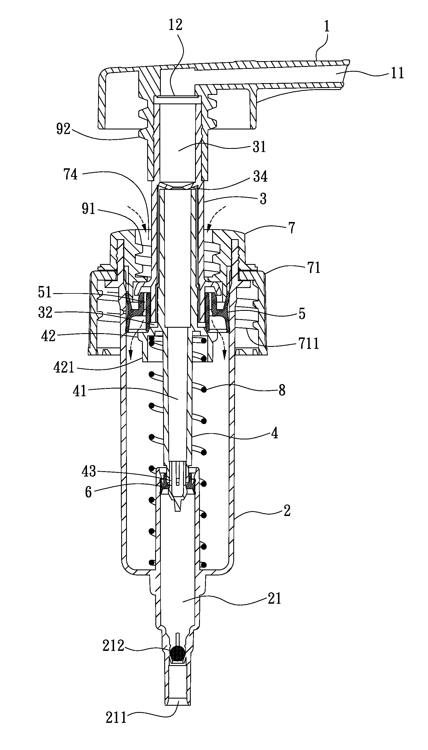
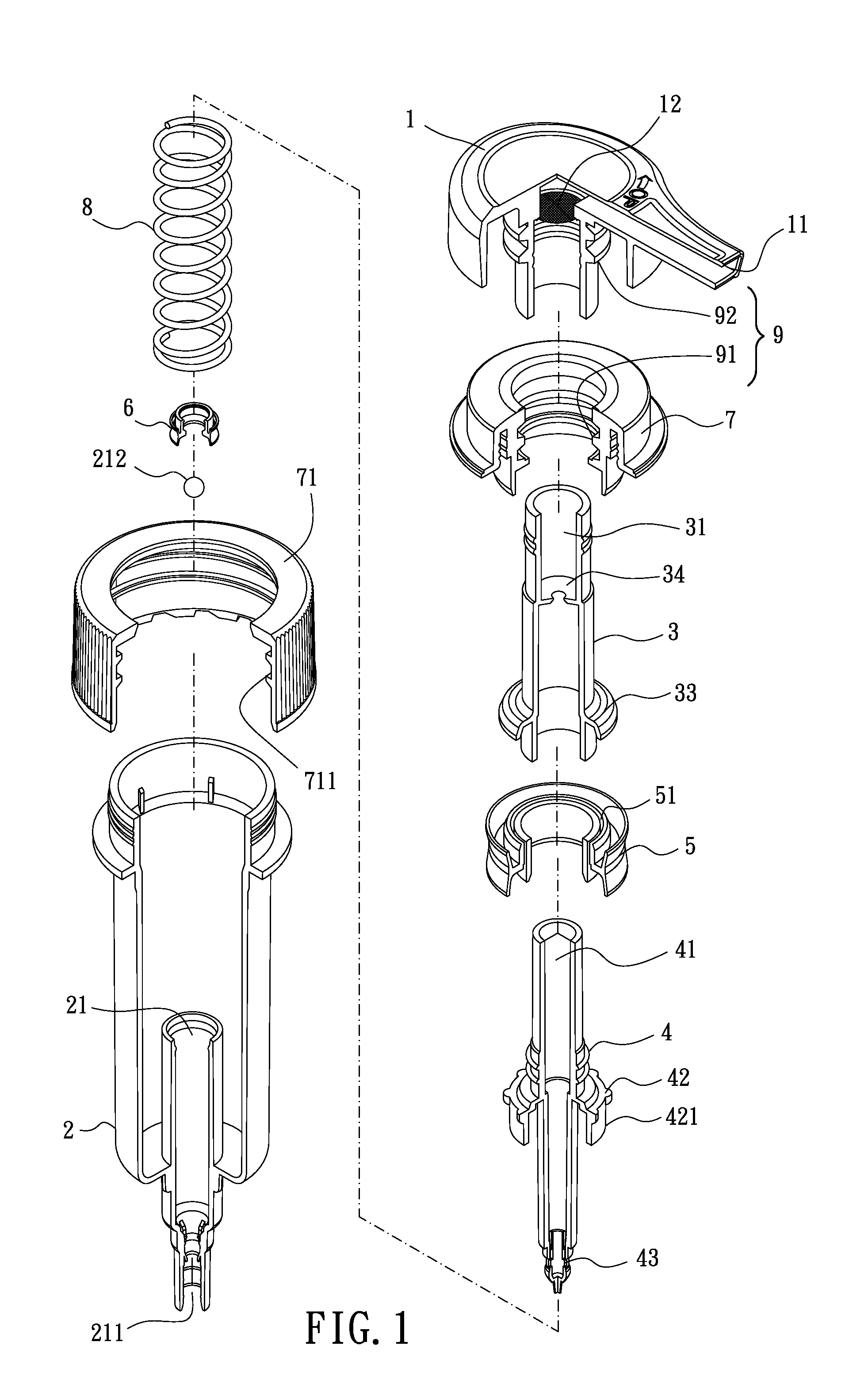
[0030]Referring to the drawings and initially to FIGS. 1-7, a foam dispensing device in accordance with a preferred embodiment of the present invention comprises an outer tube (2) axially connecting with a liquid container (not numbered), which may be a shampoo bottle, a lotion container, etc. The outer tube (2) has a tubular member (21) axially disposed therein and located at a bottom end thereof. An bottom end of the tubular member (21) extends from the bottom end of the outer tube (2) and is received in the liquid container. The tubular member (21) has a first inlet (211) defined in the bottom end thereof, such that liquid in the liquid container is guided into the tubular member (21) from the first inlet (211). A steel ball (212) is movably received in the tubular member (21) and located close to the first inlet (21). The steel ball (212) selectively seals the first inlet (211) to prevent a backflow of liquid in the tubular member (21). The outer tube (2) has a ventilating hole ...


PUM


Abstract

A foam dispensing device includes an outer tube connecting with a liquid container. A lower tube and an upper tube are partially received in the outer tube. The lower tube has a guide chamber defined therein which has a second inlet defined therein. A liquid piston is connected with the lower tube for selectively sealing the second inlet. A spring is compressibly received in the outer tube and abuts against the lower tube. The upper tube sleeves on the lower tube and has a mixing chamber defined therein for communicating with the guide chamber. An air piston movably sleeves on the upper tube and has at least one air hole defined therein for guiding air into the outer tube. A dispensing head is connected with the upper tube and has a nozzle formed thereon.

Description

BACKGROUND OF THE INVENTION[0001]1. Field of the Invention[0002]The present invention relates to a foam dispensing device, and more particularly to a device adapted to connect with a liquid container and being able to enhance mixing of air and liquid to generate foaming.[0003]2. Description of Related Art[0004]A conventional dispensing container comprises a containing body and a dispensing pump which has a nozzle disposed thereon, and cover. The dispensing pump includes a tubular device and a piston device received in the tubular device. The tubular device includes a relatively thick tube and a relatively thin tube which has a guiding tube disposed on a bottom end thereof. The piston device has a piston slidably connected with the relatively thin tube, a raising valve engaged with the piston, a piston-guiding member buckled with a top of the piston, an air piston, an air valve, and a shaft. The air piston has an inner sleeve connected with an outer periphery of the air-guiding membe...

Claims


Application Information

Patent Timeline
Patent Type & Authority Applications(United States)
IPC IPC(8): B67D7/76
CPCA47K5/14B05B7/0037B05B11/3087B05B11/3047B05B11/306B05B11/3023B05B11/1023B05B11/106B05B11/1047B05B11/1087
Inventor TSENG, SEN-LI
Owner HSIH TUNG TOOLING
Why Eureka
Try Eureka