Aircraft Floats

a technology of aircraft and floats, which is applied in the direction of floats, seaplanes, convertible alighting gear, etc., can solve the problems of reducing payload, fuel consumption, and high air drag of floats and wheels fitted to floats, so as to reduce the loss of lift from the wing, improve flight effect, and improve flight

Inactive Publication Date: 2012-05-03
RUDDUCK SAXON GRENFELL +2
View PDF10 Cites 3 Cited by
  • Summary
  • Abstract
  • Description
  • Claims
  • Application Information

AI Technical Summary

Benefits of technology

[0025]One skilled in this art would recognize that it is advantageous to close off the gap in some configurations for aerodynamic and hydrodynamic reasons. Sliding panels are one method to achieve this. The float can be split into a front float and a rear float when retracted but can be arranged for the floats to come together in the water landing position. If this instance were to occur, the floats would swing down the pivots and also move longitudinally to come together.
[0026]A further benefit of divided floats relates to lift in flight. Typical floats commonly generate useful lift in flight. This is achieved by the acceleration of the air over the top of the float relative to the airflow below. The faster air above has a drop in relative air pressure and the slower air below has an increase in pressure and the differential pressure results in lift. The downwash from the wing and flaps is directed through the opening between the front and rear floats to reduce loss of lift from the wing and damage to the floats. An additional benefit of this arrangement is by careful shaping of the rear of the front float and the front of the rear float substantial and useful lift can be generated by the accelerated airflow over the surface of the front uppermost in this arrangement. Sliding or hinged panels can resurrect the required aerodynamic or hydrodynamic shapes.

Problems solved by technology

A common problem with float planes is the high air drag associated with the floats and the wheels fitted to the floats.
This high drag increases fuel consumption and hence reduces payload, reduces speed and hence productivity and also makes the floats prone to dangerous icing up in flight.
The high fuel consumption increases operating costs and increases undesirable emissions such as carbon dioxide.
The high drag of these floats is caused by the large frontal area, large surface area, poor aerodynamic shape, sharp hydrodynamic features, and from the mounting structure.
The result is an increased air drag of approximately 45% for a floatplane over the equivalent landplane variant.
Another problem with the large retracting floats (180%) floats is the limited space below some aircraft when on their wheels on the land. FIG. 3 shows a prior art cross section through a fuselage and shows how the smaller floats can allow the wheels to operate with adequate ground clearance not possible with the large floats shown in the broken line.
Another problem encountered for the designer installing retracting floats to an aircraft is shown in FIGS. 8a, 8b and 8c. The existing wheels of an aircraft are an expensive element of the aircraft and it is desirable to retain them in use with an amphibious floatplanes.
A common arrangement is for the main wheels to retract inwardly towards the centre line of the fuselage and are thus unable to operate if the floats are retracted.
In such a configuration there can be a very strong downwash of airflow from the wing and the flaps that will impinge on the float in this position.
This can reduce the effectiveness of the wing and also damage the float.
This large safety margin results in floats that are larger than required which increases weight, air drag and other aspects such as cost.
In some instances with retracting floats, the large floats below the aircraft limit the use that can be made of the aircraft's existing wheels.

Method used


Image

  • Aircraft Floats
  • Aircraft Floats
  • Aircraft Floats

Examples


Embodiment Construction

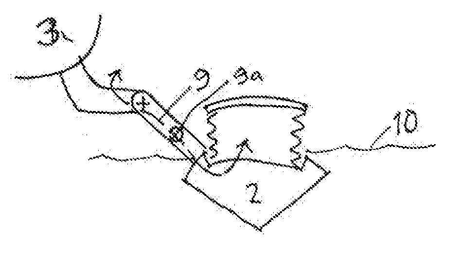
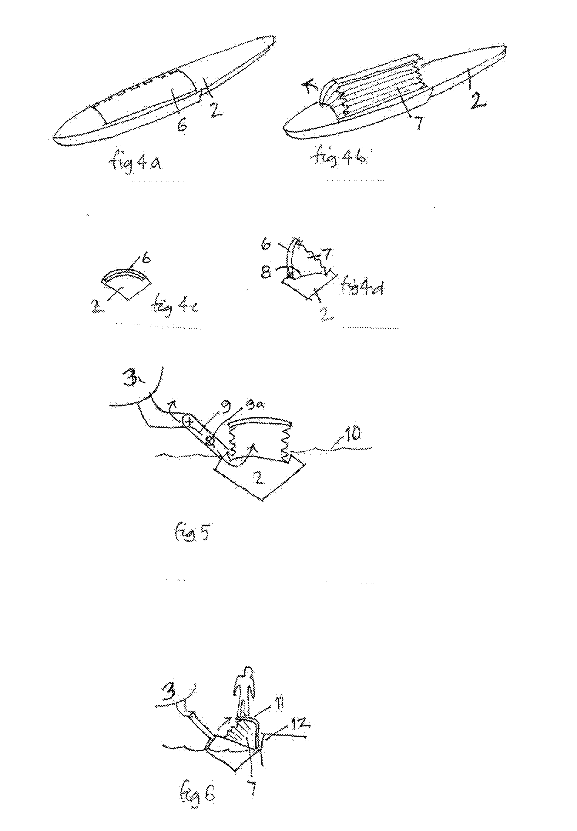
[0055]Turning to FIGS. 4a-7a, this invention relates to an improved float for use with an aircraft 3 having water landing capabilities having at least one float 2 capable of increasing / decreasing its volume arranged to at least substantially support said aircraft 1 in a floating on water status so that the fuselage of the aircraft 3 is substantially above the water 10. The float 2 has at least one hinged panel 6 that when opened reveals at least one bag 7 capable of being inflated to a desired volume.

[0056]FIGS. 4a-6 relate to a float 2 having a longitudinally hinged panel 6 that when opened reveals a bag 7 as seen in FIG. 4b. This panel is opened by a geared motor or other mechanical means (not shown). The bag 7 is a flexible bag that is attached to the underside of the panel 6 and the top of a rebate 8. As the panel 6 is opened, the volume of the float 2 can increase from 120% of the required volume to 180%, which is the volume typically needed for the floats to be operation in wa...


PUM


Abstract

This invention relates to an improved float for use with an aircraft having water landing capabilities comprising at least one float capable of increasing/decreasing its volume arranged to at least substantially support said aircraft in a floating on water status so that the fuselage of the aircraft is substantially above the water.

Description

CROSS-REFERENCE TO RELATED APPLICATIONS[0001]This claims priority to Australian Patent Provisional Application Number 2.009902360, filed May 22, 2009 and Australian Provisional Patent Application Number 20099052.35, filed on Oct. 27, 2009. These prior applications are all hereby incorporated by reference herein in their entireties.BACKGROUND OF INVENTION[0002]1. Field of the Invention[0003]This invention relates to the performance of floats on an aircraft capable of operating on water. in particular, this invention relates to an improvement to existing floats that increases the volume of a float in a manner that reduces drag on the aircraft, does not increase the weight and may, in some cases, reduce the weight of the aircraft, and does not interfere with the operation of the wheels on an aircraft.[0004]2. Background Art[0005]Aircraft are usually designed to take off and land from land—“landplanes”. Sonic of these aircraft are adapted to be able to take off and land from water which...

Claims


Application Information

Patent Timeline
Patent Type & Authority Applications(United States)
IPC IPC(8): B64C25/66B64C25/56
CPCB64C25/56
Inventor RUDDUCK, SAXON GRENFELLSMITH, ALAN JOHNTETLOW, MATTHEW ROBERT
Owner RUDDUCK SAXON GRENFELL
Why Eureka
Try Eureka