Non-contact power transmission device

Inactive Publication Date: 2012-05-03
TOYOTA IND CORP +1
View PDF1 Cites 24 Cited by
  • Summary
  • Abstract
  • Description
  • Claims
  • Application Information

AI Technical Summary

Benefits of technology

[0009]Further, the input impedance of the resonant system changes in accordance with the distance between the resonant coils and the resistance of the load. Thus, to efficiently perform non-contact power transmission, current must be supplied from the AC power supply 53 to the primary coil 54 at an appropriate frequency that corresponds to the distance between the transmission side (power transmitting) copper coil 51 and the reception side (power receiving) copper coil 52. When the non-contact power transmission device is used with the power transmitting copper coil 51 and the power receiving copper coil 52 fixed at predetermined locations, the distance between the copper coils 51 and 52 should first be measured, and the primary coil 54 should be supplied with current at a frequency that is appropriate for the distance. However, for example,

Problems solved by technology

However, when using a sensor dedicated for the measurement of the state o

Method used


Image

  • Non-contact power transmission device
  • Non-contact power transmission device
  • Non-contact power transmission device

Examples


Example

[0023]One embodiment of the present invention will now be described with reference to FIGS. 1 to 10.

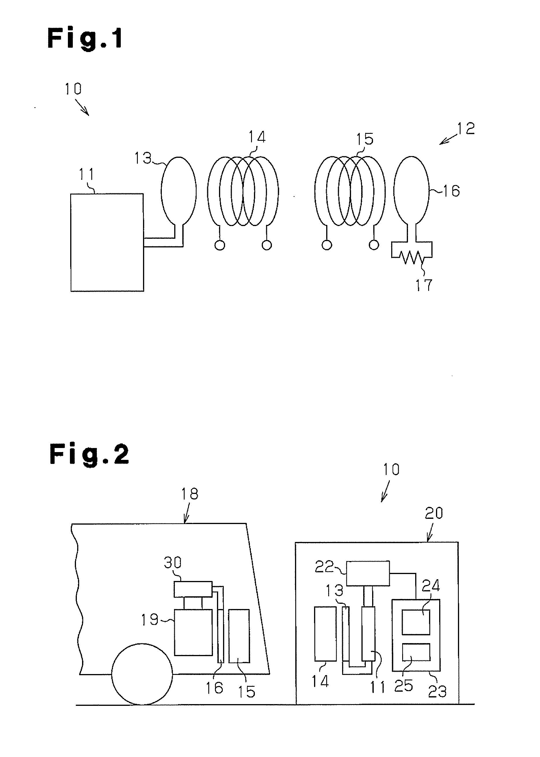
[0024]As shown in FIG. 1, a non-contact power transmission device 10 includes a resonant system 12, which transmits in a non-contact manner power supplied from an AC power supply 11. The resonant system 12 includes a primary coil 13, which is connected to the AC power supply 11, a primary resonant coil 14, a secondary resonant coil 15, and a secondary coil 16. The secondary coil 16 is connected to a load 17.

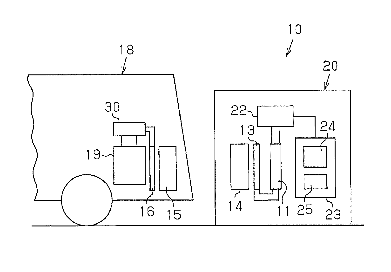
[0025]In this embodiment, the non-contact power transmission device 10 is applied to a system that performs non-contact charging on a rechargeable battery 19 installed in a movable body 18 (e.g., vehicle). As shown in FIG. 2, the secondary resonant coil 15 and the secondary coil 16 are arranged in the movable body 18. The secondary coil 16 is connected by a rectification circuit 30 to the rechargeable battery 19, which serves as the load 17. The AC power supply, the primary coil 13...


PUM


Abstract

A non-contact power transmission device includes an alternating current power supply, a resonant system, a load, an impedance measuring section and an analyzing section. The resonant system has a primary coil connected to the alternating current power supply, a primary-side resonant coil, a secondary-side resonant coil and a secondary coil. The load is connected to the secondary coil. The impedance measuring section can measure the input impedance of the resonant system. The analyzing section analyzes the measurement results obtained from the impedance measuring section.

Description

TECHNICAL FIELD[0001]The present invention relates to a non-contact power transmission device.BACKGROUND ART[0002]Non-patent document 1 and patent document 1 disclose techniques for transmitting power through resonance. For example, as shown in FIG. 11, two copper coils 51 and 52 (resonant coils) are arranged in a separated state, and one copper coil 51 transmits power to the other copper coil 52 by resonating an electromagnetic field. More specifically, the copper coils 51 and 52 generate a magnetic field that strengthens a magnetic field generated by a primary coil 54, which is connected to an AC power supply 53. A secondary coil 55 uses electromagnetic induction to retrieve the strengthened magnetic field as power from near the copper coil 52. The power is supplied to a load 56. When the copper coils 51 and 52, which have a diameter of 30 cm, are separated from each other by two meters, it has been confirmed that a 60 watt lamp, which serves as the load 56, can be illuminated.[00...

Claims


Application Information

Patent Timeline
IPC IPC(8): H02J7/00G01R27/28B60L5/00B60M7/00
CPCH01M10/44H02J5/005Y02T10/7005Y02T10/705Y02T90/122B60L50/66G01B7/14Y02T10/7072H02J50/12H02J7/025B60L53/12Y02T90/14B60L53/126Y02T10/70Y02E60/10H02J50/90H02J7/00034Y02T90/12H02J7/00
Inventor TAKADA, KAZUYOSHISUZUKI, SADANORINAKATA, KENICHISAKODA, SHIMPEIYAMAMOTO, YUKIHIROICHIKAWA, SHINJIISHIKAWA, TETSHUHIRO
Owner TOYOTA IND CORP
Why Eureka
Try Eureka