Connector assembly for electrical and mechanical interconnection of modules

Inactive Publication Date: 2012-05-03
ZF FRIEDRICHSHAFEN AG
View PDF5 Cites 5 Cited by
  • Summary
  • Abstract
  • Description
  • Claims
  • Application Information

AI Technical Summary

Benefits of technology

[0012]In a present embodiment of the invention, the first module is a transmission control module and the second module is a transmission display module. In this embodiment, the transmission display module includes a display panel connected with the printed circ

Problems solved by technology

A recurring problem with such modular systems, however, arises from the need to electrically and / or electronically interconnect the various modules of the vehicle systems with one another, which typically requires various forms of vehicle interconnection buses, module-to-module buses and / or wiring harnesses and connectors.
Such interconnections typically require the interconnection of wiring harnesses, cables, buses and / or connectors which, in turn, result in increases system costs and complexity and generally reduces the connection reliability due to the possibly failure of the interconnection components, such as cables and connectors, in adverse environments, such as in a vehicle.
A recurring problem with the direct electrical interconnection of such mechanically interconnected modules by, for example, directly mating electrical connectors mounted on the modules arises, however, from the tolerances or “play” necessary and inherent for joining mechanical components with one another and, in particular, the potential ranges of cumulative tolerances of the connected modules.
That is, all mechanical components which interconnect with one another inherently have a range of tolerances and when assembling modules with one another and / or with other components, the tolerances of the various components can be cumulative thereby rendering it more difficult to accurately and reliably assemble components, such system modules, with one another.
In the case of electrical or electronic connections between adjacent modules, the component tolerances, including the cumulative tolerances on the mechanical mating elements of two modules and their cumulative tolerances for the electrically or electronically mating elements, such as electrical connectors of various types, may individually or in combination with one another prevent an adequate electrical connection of the electrical connectors of the two modules with one another or may possibly result in damage to the electrical connections when such connection is attempted.

Method used


Image

  • Connector assembly for electrical and mechanical interconnection of modules
  • Connector assembly for electrical and mechanical interconnection of modules
  • Connector assembly for electrical and mechanical interconnection of modules

Examples


Embodiment Construction

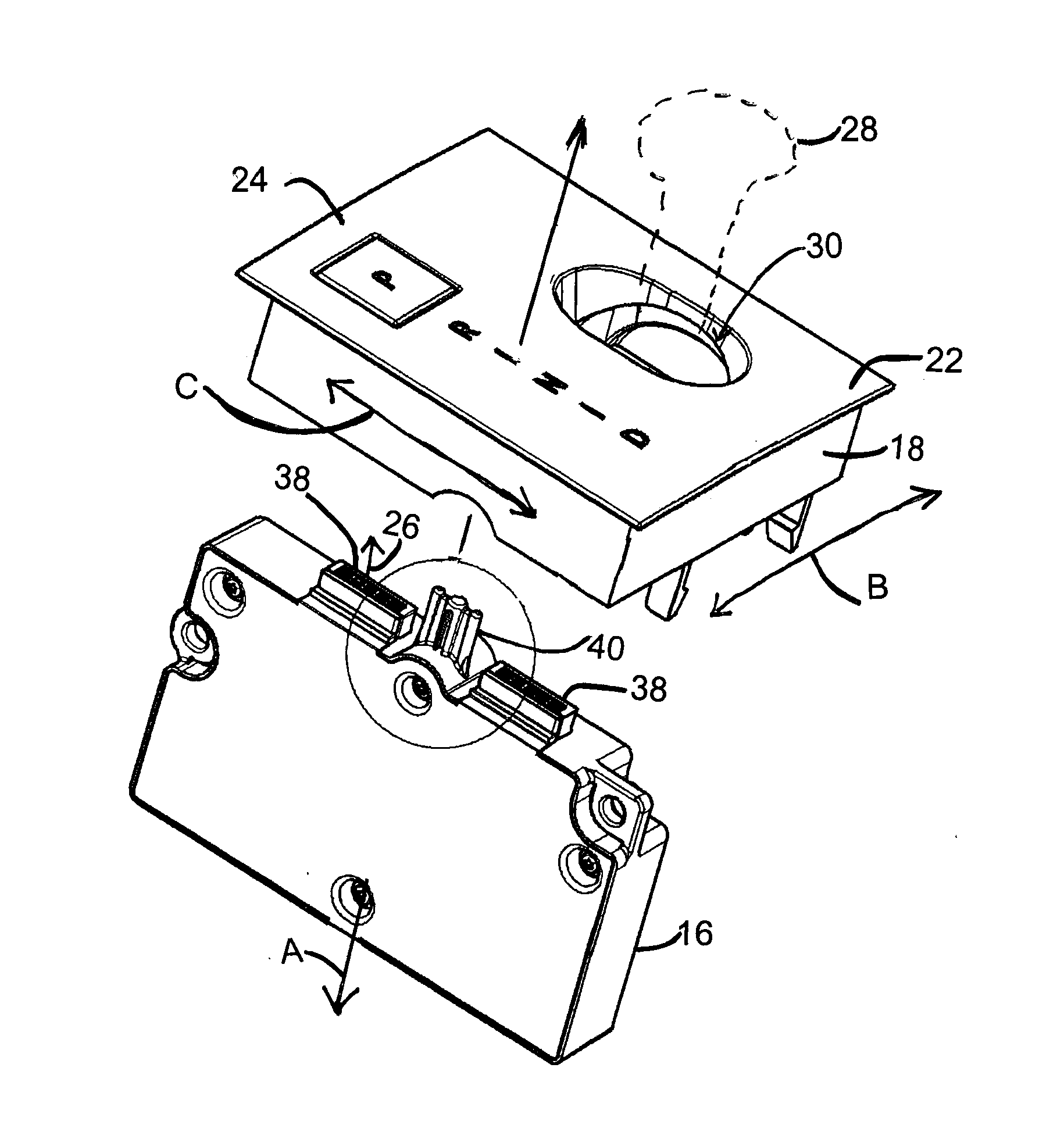
[0024]The following describes the connection system, according to the present invention, for electrical and mechanical interconnection of adjacent first and second modules with one another. In this embodiment, the exemplary connection system comprises a transmission control module which is mechanically and electrically interconnected with the adjacent transmission display module.

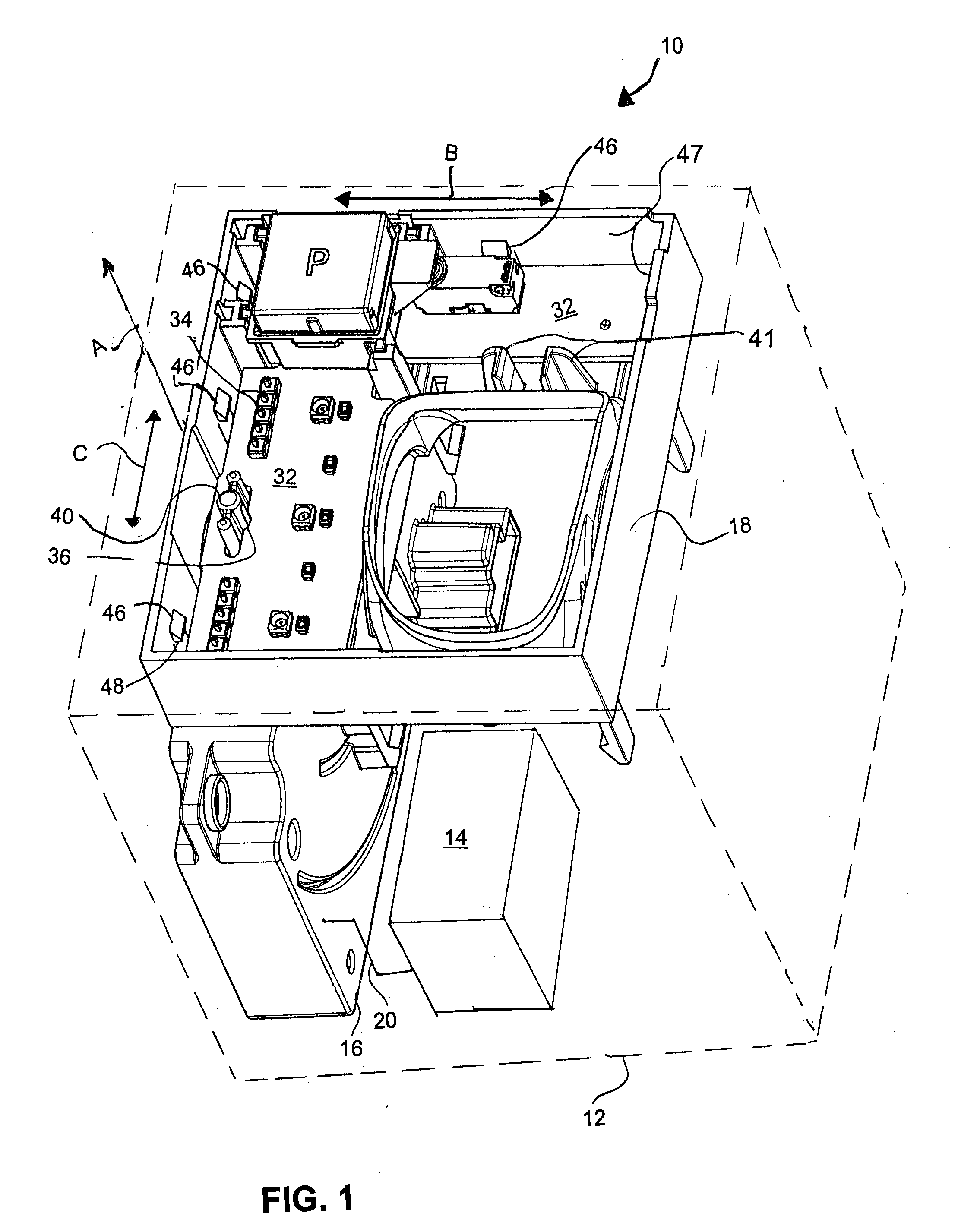
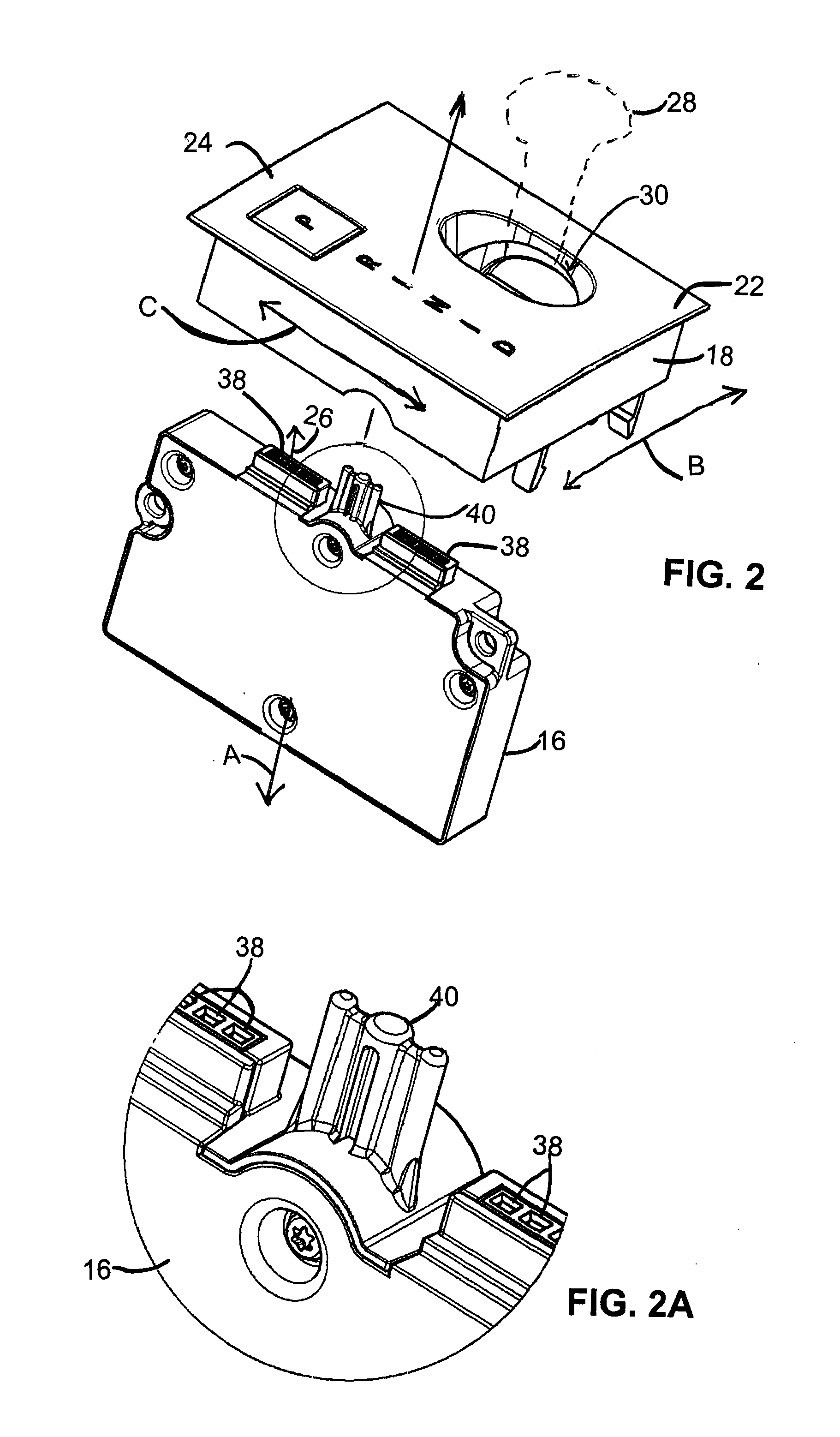
[0025]With reference to FIG. 1, a module assembly 10 for a system, such as a transmission control and display system 12 for a transmission 14 of a vehicle, is shown in which a transmission control module 16 is mechanically and electrically interconnected with a transmission display module 18. As generally shown in FIGS. 1, 2, 2A, 3 and 4, the transmission control module 16 is typically responsive to a driver input for selecting a gear change operation(s) for the vehicle by, for example, a shift lever 28 (see FIG. 2), and possibly in response to one or more other inputs received from other modules of the vehi...


PUM


Abstract

A connector for electrical and mechanical interconnection of first and second mechanically adjacent modules with one another. The first module includes a first electrical connector and an alignment pin and the second module includes a printed circuit board floatingly and displacably mounted on the second module with at least one alignment hole aligned for alignment with the alignment pin of the first module and a second electrical connector aligned for engagement with a corresponding first electrical connector of the first module. During assembly, the alignment pin of the first module engages the alignment hole of the second module and displaces the printed circuit board to align the second electrical connector with the first electrical connector.

Description

FIELD OF THE INVENTION[0001]The present invention relates to a connector assembly for assisting with mechanical and electrical interconnection of adjacent modules with one another and, in particular, for the electrical interconnection of a display module with a mechanically adjacent control module.BACKGROUND OF THE INVENTION[0002]Many electrical and mechanical systems are constructed on a module basis. That is, related functions or groups of related functions of a system are implemented in separate modules which are then electrically and / or mechanically interconnected with one another so as to cooperate in performing the various functions and operations of the system.[0003]An example of such is a transmission system for a motor vehicle in which the system may include a transmission control module and a transmission display module. In such systems, the transmission control module is typically responsive to driver inputs for selecting gear change operations of the vehicle by, for exam...

Claims


Application Information

Patent Timeline
IPC IPC(8): H05K7/00
CPCF16H59/105F16H63/42F16H2057/005B60K37/02B60K35/60
Inventor SCHOBER, THOMASBECK, WERNERDEICHLER, THOMAS
Owner ZF FRIEDRICHSHAFEN AG
Why Eureka
Try Eureka