Ceiling mount lamp having a fixing structure capable of assisting heat dissipation

a technology of fixing structure and ceiling lamp, which is applied in the direction of fixed installation, lighting and heating apparatus, instruments, etc., can solve the problems of not meeting the demand of environmental protection, foregoing luminaries disadvantageously consume much energy, and crowding and discordant spaces, etc., to achieve enhanced illumination, enhanced heat dissipation, and light guide performance of light guide plate

Inactive Publication Date: 2012-05-03
ELSA OPTICAL TECH +1
View PDF2 Cites 5 Cited by
  • Summary
  • Abstract
  • Description
  • Claims
  • Application Information

AI Technical Summary

Benefits of technology

[0009]The lighting unit is installed between the frame body and the back plate of the fixing unit. The lighting unit comprises a reflective sheet, a light guide plate, and a diffusion sheet. The reflective sheet is installed on the back plate of the fixing unit, and the light guide plate installed on the reflective sheet. At least one side of the light guide plate is provided with a circuit board on which an LED unit is disposed. Light emitted by the LED unit is reflected by the reflective sheet, and the light guide plate is provided for guiding the light emitted by the LED unit and reflected from the reflective sheet. The diffusion sheet is installed on the light guide plate and provided for further diffusing and softening the light emitted by the LED unit and reflected from the reflective sheet.
[0010]At least one side between the frame body and the back plate of the fixing unit is mounted with a U-shaped fixing member. One outer surface of the U-shaped fixing member is fastened with the circuit board, and another outer surface of the U-shaped fixing member is provided with at least a hook part, which provides an elastic force to push against the circuit board and the LED unit, such that the LED unit is pressed close to the light guide plate, thereby the light guide performance of the light guide plate and the illumination can be enhanced.
[0011]By means of the above technical solutions of the present invention, when the LED unit is lit, the heat generated by the LED unit is transferred through the circuit board to the U-shaped fixing member. An inward recessed space defined through the U-shaped fixing member is helpful for heat dissipation by radiation. Moreover, the U-shaped fixing member can also transfer heat by conduction to the frame body and the back plate. That will enhance the heat dissipation from the ceiling mount lamp to the outside. With effective heat dissipation, all electric parts of the ceiling mount lamp in accordance with the present invention, such as the LED unit and the circuit board, can prevent from damage due to heat accumulation therein. Therefore, the service life of all electric parts can be prolonged and the illumination of the LED unit is more stable.

Problems solved by technology

When such a chandelier is provided in a house with a 2.7 m floor height, the space may be looked crowd and discordant.
Both of the foregoing luminaries disadvantageously consume much energy, and do not satisfy the demand of environmental protection.
However, a conventional LED ceiling mount lamp often has shortages of poor heat dissipation which may reduce the service life of the LED, and the LED and a light guide plate of the ceiling mount lamp is not sufficiently pressed close to each other.
A gap between the LED and the light guide plate would result in that the light guide performance of the light guide plate and the illumination are not able to be efficiently enhanced.

Method used


Image

  • Ceiling mount lamp having a fixing structure capable of assisting heat dissipation
  • Ceiling mount lamp having a fixing structure capable of assisting heat dissipation
  • Ceiling mount lamp having a fixing structure capable of assisting heat dissipation

Examples


Embodiment Construction

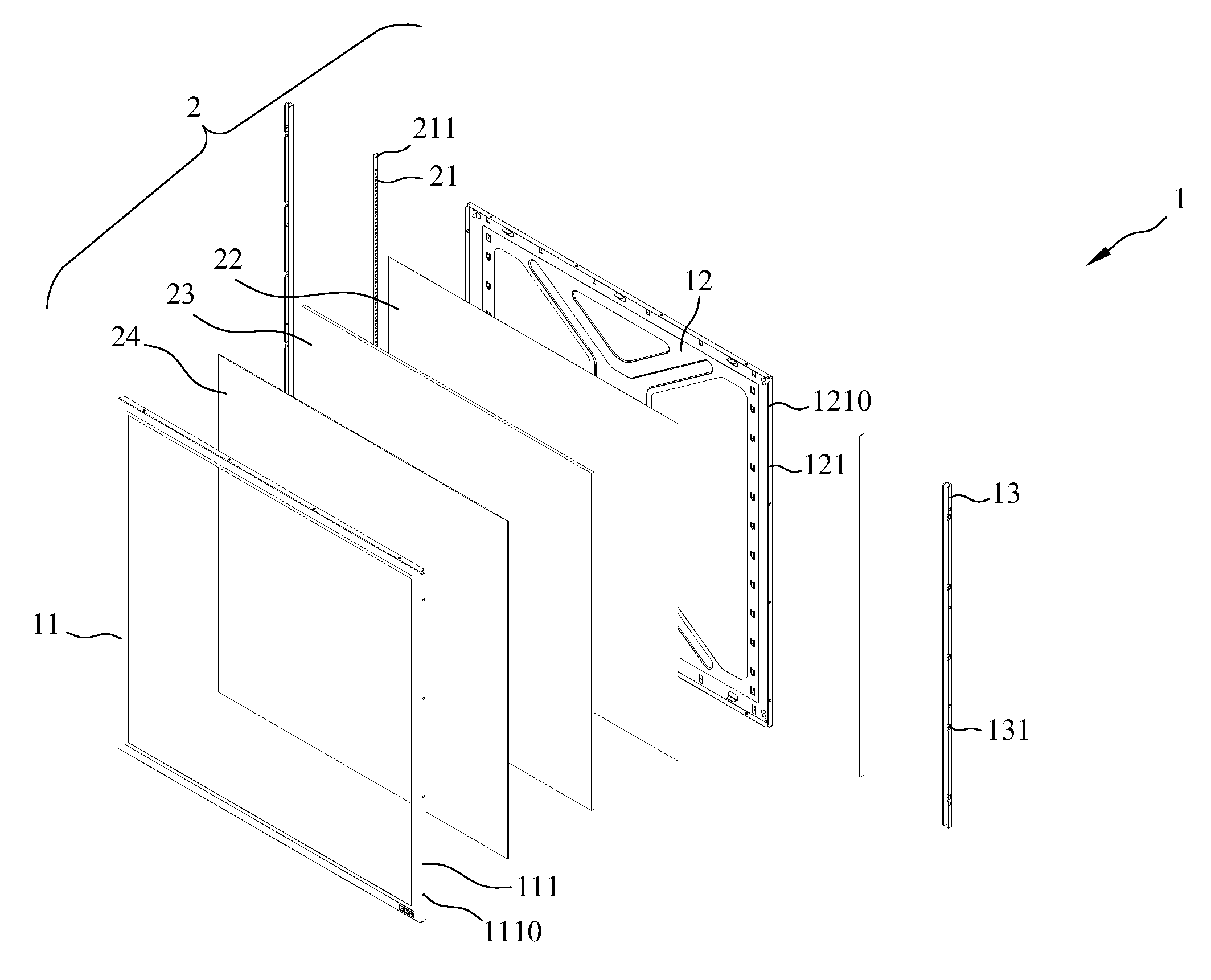
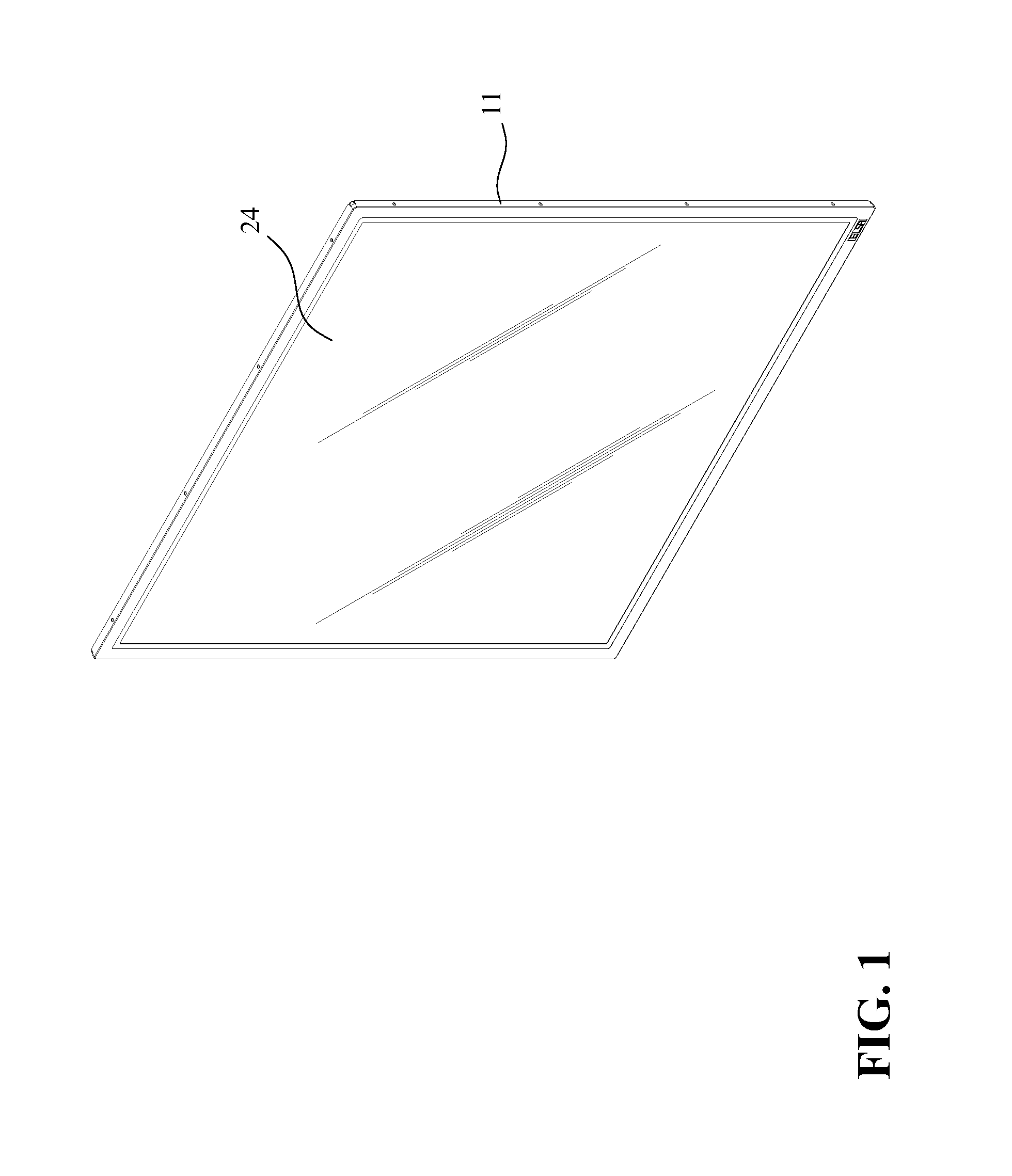
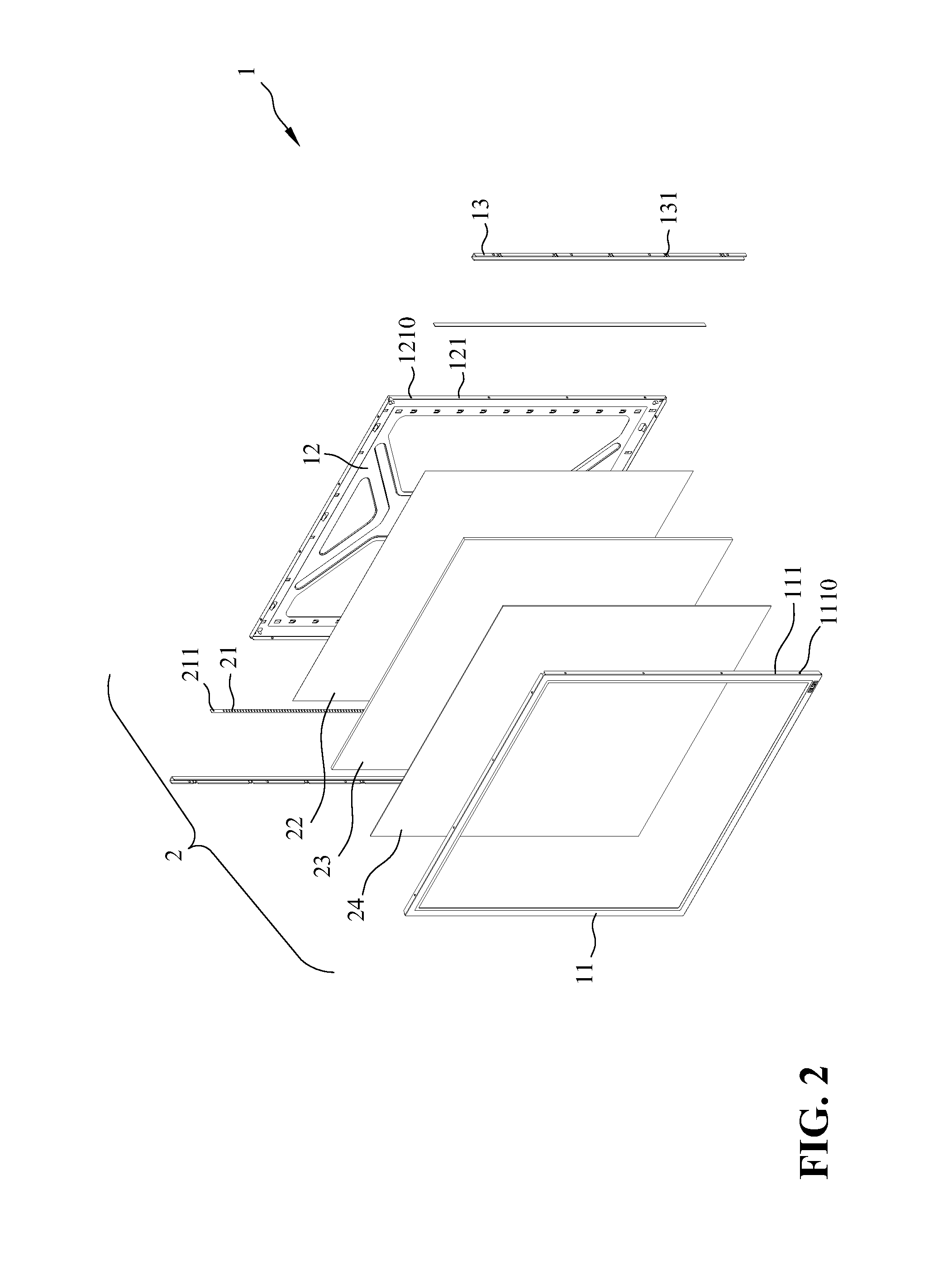
[0017]Referring to FIG. 1 to FIG. 4, a ceiling mount lamp having a fixing structure capable of assisting heat dissipation according to the present invention comprises a fixing unit 1 and a lighting unit 2.

[0018]The fixing unit 1 includes a frame body 11 having folded edges 111 equipped with at least one hook hole 1110, and a back plate 12 assembled with the frame body 11 and having buckling edges 121 equipped with at least one buckling hole 1210.

[0019]The lighting unit 2 is installed between the frame body 11 and the back plate 12 of the fixing unit 1. The lighting unit 2 includes a reflective sheet 22, a light guide plate 23, and a diffusion sheet 24. The reflective sheet 22 is installed on the back plate 12 of the fixing unit 1, and the light guide plate 23 is installed on the reflective sheet 22. At least one side of the light guide plate 23 is installed with a circuit board 211 on which an LED unit 21 is disposed. Light emitted by the LED unit 21 is reflected by the reflective s...


PUM


Abstract

A ceiling mount lamp having a fixing structure capable of assisting heat dissipation is disclosed. The ceiling mount lamp includes a fixing unit including a frame body and a back plate, and a lighting unit installed between the frame body and the back plate. At least one side of the light guide plate is provided with a circuit board on which an LED unit is disposed, and at least one side between the frame body and the back plate of the fixing unit is mounted with a U-shaped fixing member. One outer surface of the U-shaped fixing member is fastened with the circuit board, and another outer surface of the U-shaped fixing member is provided with at least a hook part, which provides an elastic force to push against the circuit board and the LED unit, such that the LED unit is pressed close to the light guide plate.

Description

BACKGROUND OF THE INVENTION[0001]1. Field of the Invention[0002]The present invention relates to a ceiling mount lamp having a fixing structure, especially a U-shaped fixing structure having functions of heat conduction and dissipation, and buckling.[0003]2. The Prior Arts[0004]Currently, luminaries mounted on ceilings are often used in home or offices. Such luminaries typically include chandeliers and ceiling mount fluorescent lamps. Generally, a typical chandelier often occupies a large space. When such a chandelier is provided in a house with a 2.7 m floor height, the space may be looked crowd and discordant. As to office used lamps, in most circumstances, ceiling mount fluorescent lamps are selected. A typical ceiling mount fluorescent lamp adapted for office use is a fluorescent lamp tube secured in a frame. Specifically, the frame is a flat metal-made π-shaped structure. The fluorescent lamp tube is secured inside the space defined in the frame, and a rectifier is secured on a...

Claims


Application Information

Patent Timeline
Patent Type & Authority Applications(United States)
IPC IPC(8): F21S8/04
CPCF21S8/04F21V15/01G02B6/0085F21Y2115/10F21Y2105/00F21V2200/20G02B6/009
Inventor CHEN, TSU-WANG
Owner ELSA OPTICAL TECH
Why Eureka
Try Eureka