
Apparatus and method for dynamically controlling integration time of depth camera for accuracy improvement

a technology of integration time and depth camera, applied in the field of high-quality depth image acquisition, can solve the problem that the maximum value of integration time when an image is captured in real-time may be limited by a desired frame rate, and achieve the effect of efficient improvement of depth image accuracy

Active Publication Date: 2012-05-03
SAMSUNG ELECTRONICS CO LTD
View PDF10 Cites 12 Cited by
  • Summary
  • Abstract
  • Description
  • Claims
  • Application Information

AI Technical Summary

Benefits of technology

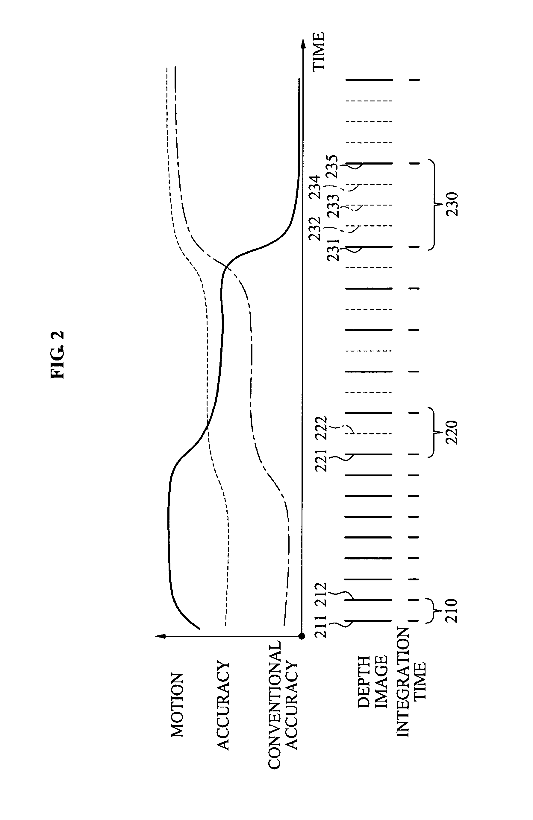
[0018]According to example embodiments, it is possible to improve an accuracy of a depth image by dynamically adjusting an integration time of a depth camera based on a motion of the depth image.
[0020]Furthermore, according to example embodiments, it is possible to efficiently improve an accuracy of a depth image by interpolating the depth image lost due to an adjustment of an integration time, even when a constant frame rate needs to be maintained.

Problems solved by technology

However, a maximum value of an integration time when an image is captured in real-time may be limited by a desired frame rate.

Method used


Image

  • Apparatus and method for dynamically controlling integration time of depth camera for accuracy improvement
  • Apparatus and method for dynamically controlling integration time of depth camera for accuracy improvement
  • Apparatus and method for dynamically controlling integration time of depth camera for accuracy improvement

Examples


Embodiment Construction

[0027]Reference will now be made in detail to example embodiments, examples of which are illustrated in the accompanying drawings, wherein like reference numerals refer to the like elements throughout. Example embodiments are described below to explain the present disclosure by referring to the figures.

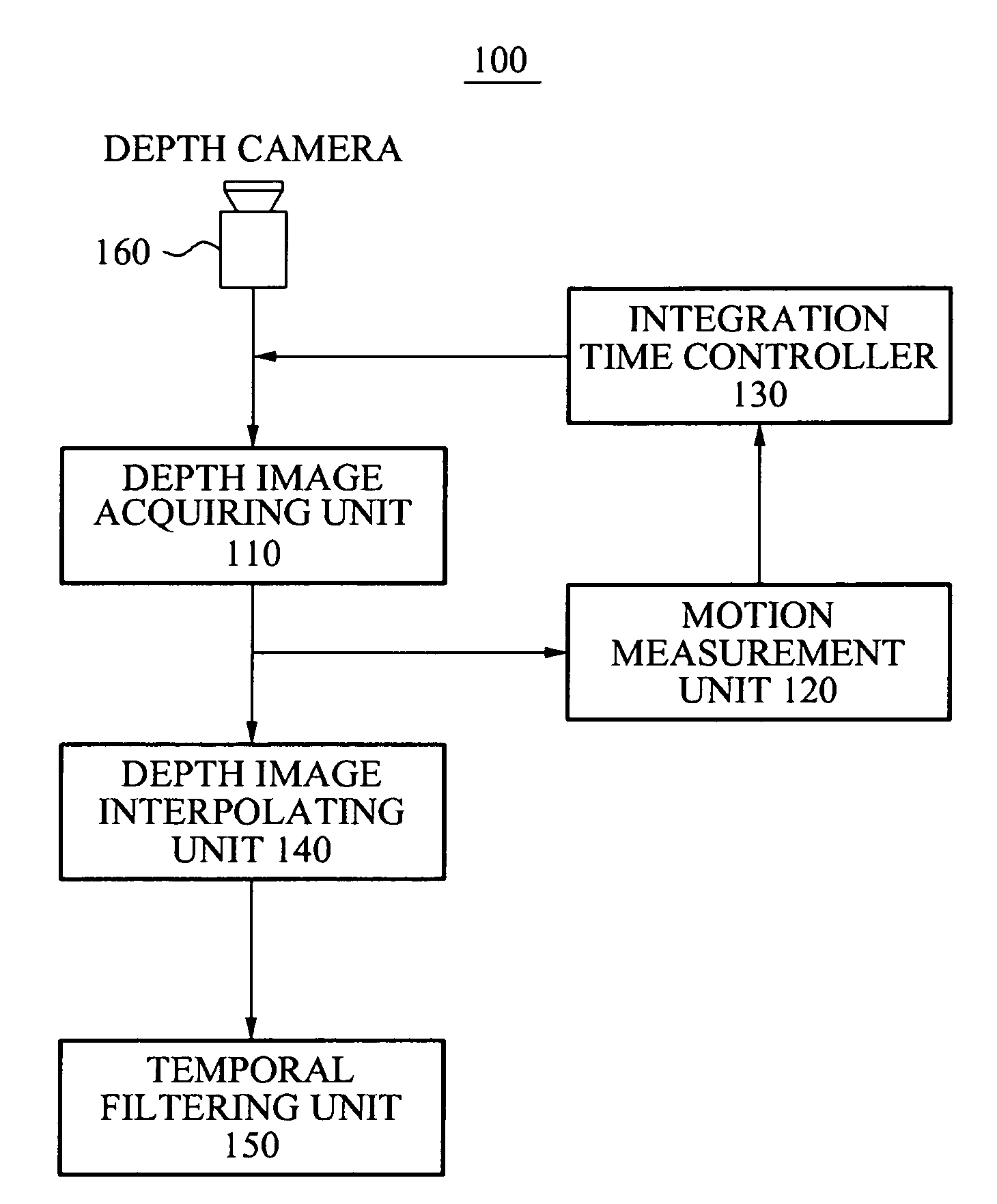
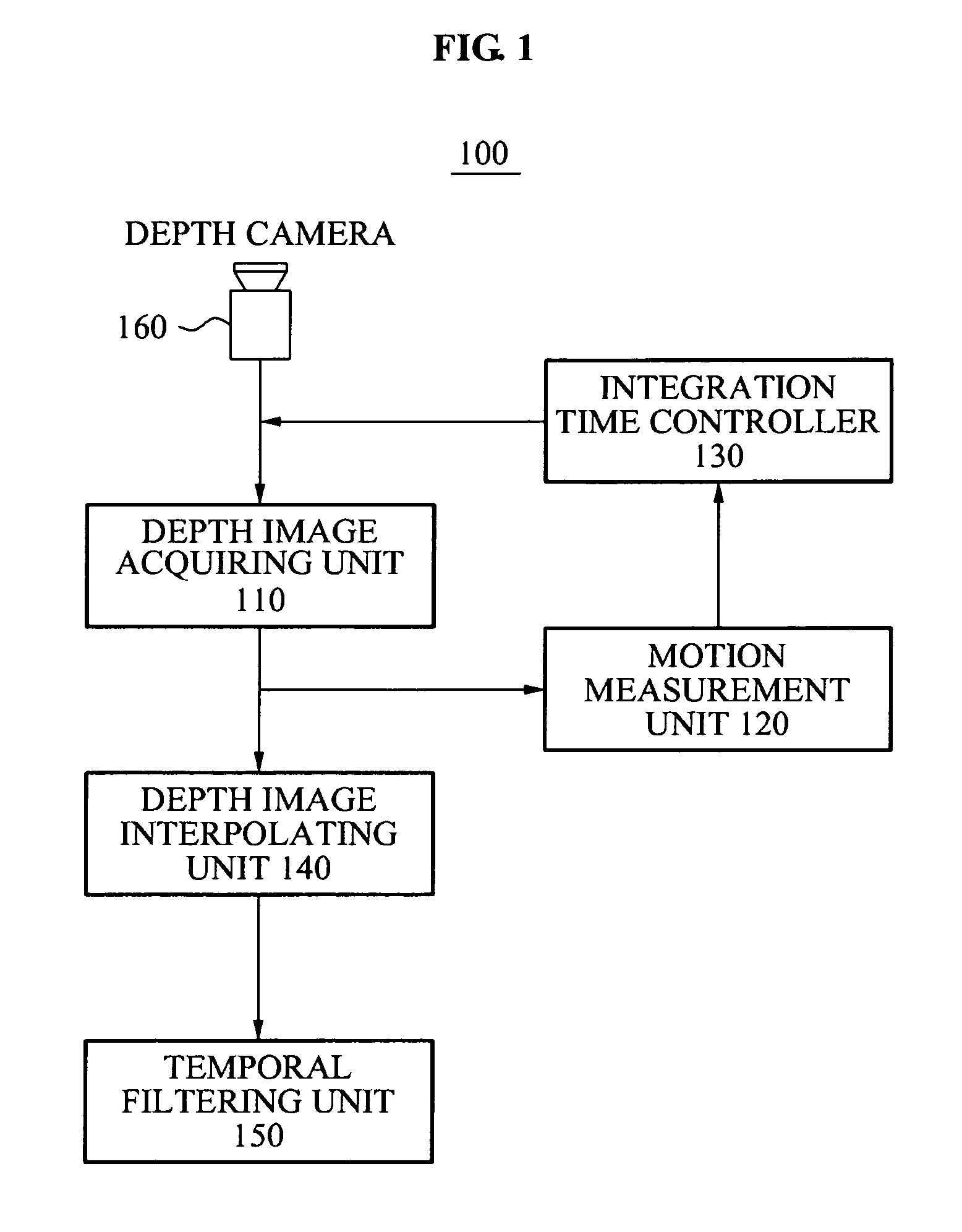
[0028]FIG. 1 is a block diagram of an integration time dynamic control apparatus 100 for dynamically controlling an integration time of a depth camera according to example embodiments. Referring to FIG. 1, the integration time dynamic control apparatus 100 may include a depth image acquiring unit 110, a motion measurement unit 120, an integration time controller 130, a depth image interpolating unit 140, a temporal filtering unit 150, and a depth camera 160.

[0029]The depth camera 160 may employ a Time-of-Flight (TOF) scheme. The depth camera 160 may generate a depth image by capturing an object based on an integration time set in advance. During the integration time, electrons may be ...


PUM


Abstract

An integration time dynamic control apparatus and method for dynamically controlling an integration time of a depth camera based on a motion of a depth image, are provided to improve an accuracy of the depth image. The integration time dynamic control apparatus may measure a motion of a depth image acquired from the depth camera, may determine whether the measured motion is greater than or equal to a reference value set in advance, and may control the integration time of the depth camera based on a result of the determination, thereby improving the accuracy of the depth image.

Description

CROSS-REFERENCE TO RELATED APPLICATIONS[0001]This application claims the benefit of Korean Patent Application No. 10-2010-0108511, filed on Nov. 3, 2010, in the Korean Intellectual Property Office, the disclosure of which is incorporated herein by reference.BACKGROUND[0002]1. Field[0003]Example embodiments of the following description relate to a method of acquiring a depth image with a high accuracy.[0004]2. Description of the Related Art[0005]An accuracy of a depth image acquired from a depth camera employing a Time-of-Flight (TOF) scheme varies depending on an internal factor such as a camera frequency and an integration time, as well as an external factor such as materials or colors of an object.[0006]In particular, an accuracy of an acquired depth image increases, as an integration time becomes longer. However, a maximum value of an integration time when an image is captured in real-time may be limited by a desired frame rate.SUMMARY[0007]An apparatus for dynamically controllin...

Claims


Application Information

Patent Timeline
IPC IPC(8): G06K9/00
CPCG01S17/89G01S17/50G01S17/894
Inventor LEE, SEUNG KYUKIM, DO KYOONLEE, KEE CHANGKANG, BYONG MIN
Owner SAMSUNG ELECTRONICS CO LTD
Learn More