Lifting fitting

Active Publication Date: 2012-05-03
SIEMENS GAMESA RENEWABLE ENERGY AS
View PDF14 Cites 12 Cited by
  • Summary
  • Abstract
  • Description
  • Claims
  • Application Information

AI Technical Summary

Benefits of technology

[0006]It is therefore an object of the invention to provide a simple lifting fitting which avoids the problems outlined above.
[0010]The favourable arrangement of the slotted holes allows the inventive lifting fitting to be attached to elements with a wide range of sizes. In the case of circular elements, the lifting fitting can be used to lift into place any element with a diameter in a wide range of diameters. An obvious advantage of the lifting fitting according to the invention is that it comprises essentially only one piece. Also, the lifting fitting itself does not require any adjustment before attaching it to an element to be lifted. Therefore, the assembly process can be completed faster. Furthermore, since the lifting fitting does not require any precisely milled parts such as grub screws or threads, its manufacture is particularly economical and straightforward.
[0012]In contrast to prior art lifting fittings, the method according to the invention is particularly straightforward and fast. Since there are no small parts such as sleeves, grub screws etc. to be dismantled, the lifting fitting according to the invention can very quickly be connected to an element to be lifted, and can equally quickly be removed again.
[0024]The lifting fitting, when used to lift large and heavy elements, is preferably equipped with some suitable means for attaching it to a hoisting apparatus such as industrial crane rigging. Therefore, in a further preferred embodiment of the invention, the connection means of the lifting fitting preferably comprises an eyelet or other suitable through-opening in the side wall for connecting a lifting cable or a shackle. The eyelet is preferably dimensioned to accommodate a cable or shackle that is large enough to bear the weight of the largest element to be lifted. The eyelet can preferably be reinforced by a grommet or other suitable means to reduce wear on both eyelet and cable or shackle. Once the lifting fitting has been connected by a worker as described above to the element to be lifted, a steel cable or other lifting means can be connected, for example by means of a shackle, to the lifting fitting through the eyelet. Thereafter, the element can be raised up and hoisted into place. Once the element is in place, a worker can connect the lower part of this element to the upper part of a predecessor element and then proceed to disconnect the lifting fittings.

Problems solved by technology

While this approach allows the use of a single type of lifting fitting, this fitting requires the use of multiple sleeves, and the process of connecting such fittings to each tower section and then disconnecting them again is extremely time-consuming.
The relatively large number of small parts—sleeves, struts, grub screws, etc.—can result in problems if a part is dropped or mislaid.
Furthermore, since outdoor construction sites are exposed to all kinds of weather conditions, the small parts may become encrusted with dirt or salt over time, so that they may become jammed or blocked.

Method used


Image

  • Lifting fitting
  • Lifting fitting
  • Lifting fitting

Examples


first embodiment

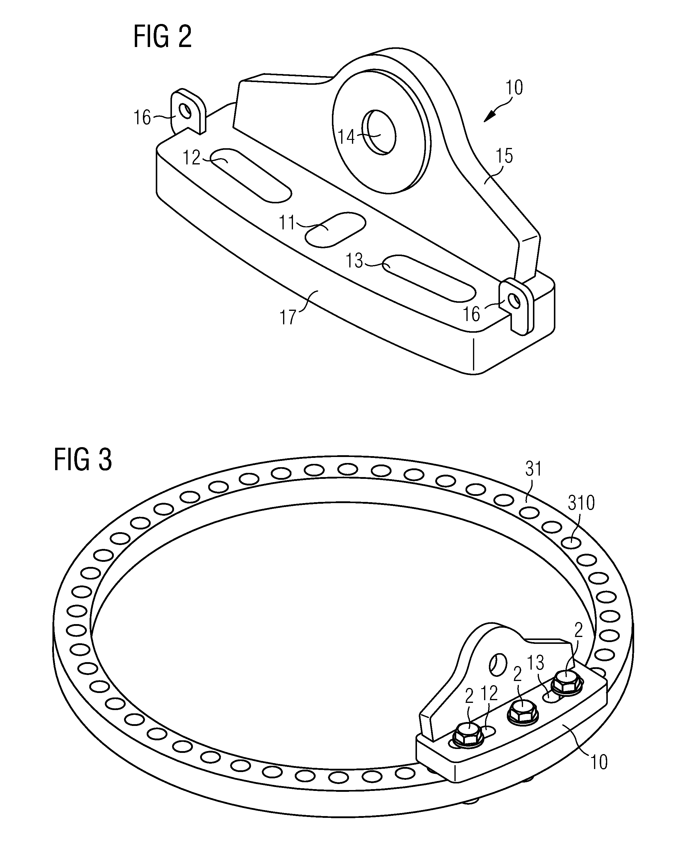
[0041]FIG. 2 shows a lifting fitting 10 according to the invention. This lifting fitting 10 comprises a base plate 17 and a side wall 15 with a connecting means 14 in the form of an opening 14 or eyelet 14 for connection to a shackle and lifting apparatus. A pair of smaller eyelets 16 located at either end of the side wall 15 is used in handling the fitting 10 during connection to a part to be lifted.

[0042]The lifting fitting 10 according to the invention is shown to have a first slotted hole 11 and two further slotted holes 12, 13 facing away from the first slotted hole 11. This arrangement allows degrees of freedom in essentially two directions for bolts inserted through these slotted holes 11, 12, 13.

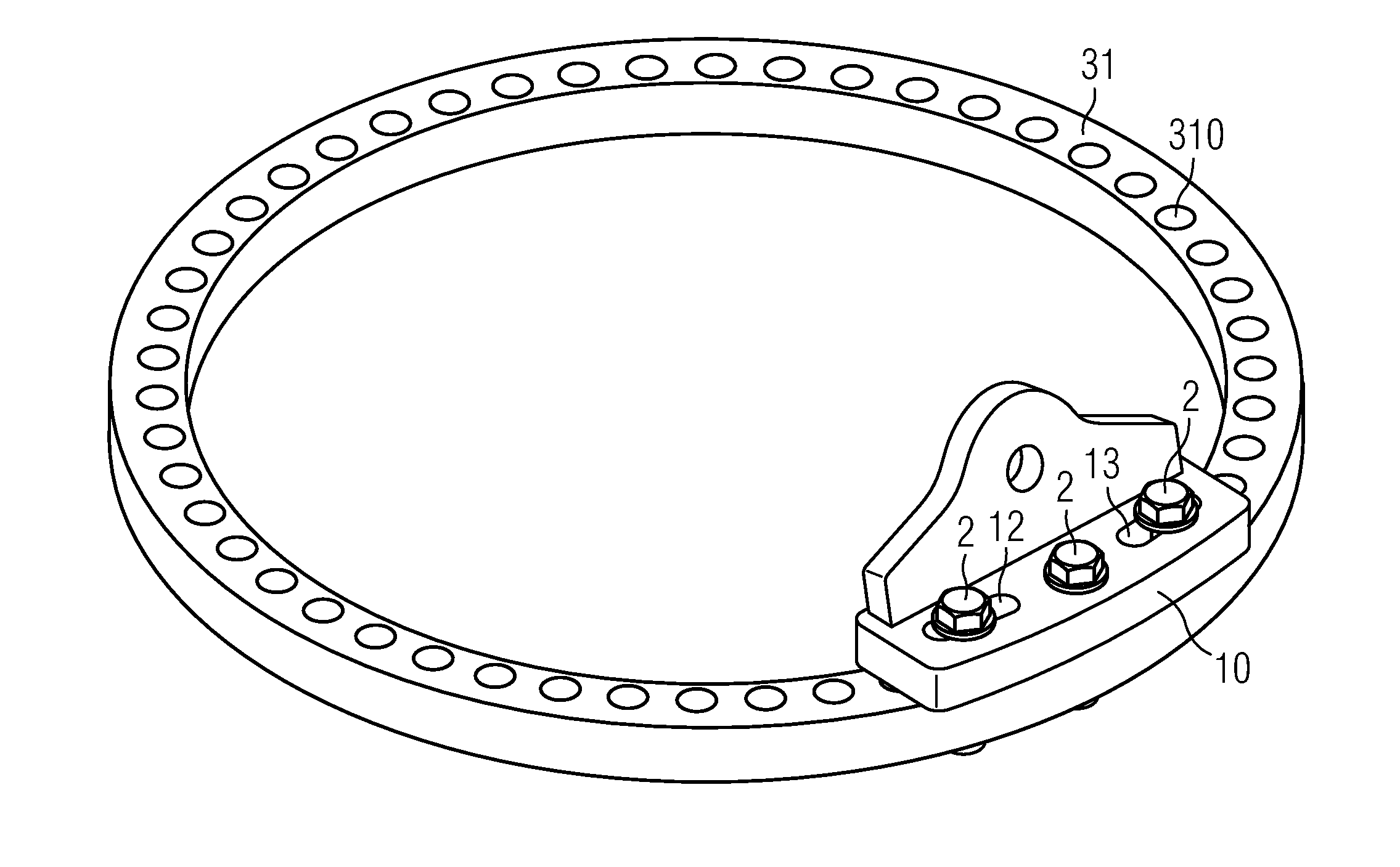
[0043]This is illustrated with the aid of the following figures. In FIG. 3, the lifting fitting 10 is shown connected to an assembly means 31 or flange 31 of a circular tower section. For the sake of simplicity, only the flange 31 is shown. A series of holes 310 is arranged around th...

third embodiment

[0048]FIG. 9 shows the lifting fitting 30 according to the invention. Here, the lifting fitting 30 has two central slotted holes 11, and this pair of central slotted holes 11 is flanked on both sides by a pair of outer slotted holes 12, 13. This arrangement of slotted holes 11, 12, 13 may allow a greater range of differences in the sizes of the elements to be lifted by the lifting fitting 30, or may allow the lifting fitting 30 to be used with elements having assembly means with widely varying or even irregular hole spacings.

[0049]Although the present invention has been disclosed in the form of preferred embodiments and variations thereon, it will be understood that numerous additional modifications and variations could be made thereto without departing from the scope of the invention. While the assembly of wind turbine towers made of steel tower sections was used as a basis for the description, the lifting fitting according to the invention may be used to good effect in assembling ...


PUM


Abstract

A lifting fitting for lifting a series of elements of different sizes in a wind turbine is proposed. The lifting fitting has a base plate having at least one central slotted hole shaped to accommodate a fastener for fastening the lifting fitting to an element to be lifted, at least two outer slotted holes each shaped to accommodate a further fastener for fastening the lifting fitting to an element to be lifted. The outer slotted holes are arranged transverse to the central slotted hole. The lifting fitting is connected to a lifting apparatus for lifting the element. A method of assembling the series of elements is proposed. The elements are successively lifted into place. The lifting fitting can be used in the assembly of a wind turbine tower having individually liftable tower sections for lifting the tower sections into place.

Description

CROSS REFERENCE TO RELATED APPLICATIONS[0001]This application is the US National Stage of International Application No. PCT / EP2009 / 067714, filed Dec. 22, 2009 and claims the benefit thereof. The International Application claims the benefits of a provisional patent application filed on Jul. 24, 2009, and assigned application Ser. No. 61 / 228,196. Both of the applications are incorporated by reference herein in their entirety.FIELD OF THE INVENTION[0002]The invention describes a lifting fitting for use in lifting a series of elements of different sizes. The invention further describes a method of assembling a series of elements of different sizes. The invention also describes the use of a lifting fitting in the assembly of a tower.BACKGROUND OF THE INVENTION[0003]Many wind turbines are constructed as hollow steel towers made of prefabricated tower sections. The tower sections, which are generally made of steel and may be several tens of metres in length and several metres in diameter, ...

Claims


Application Information

Patent Timeline
IPC IPC(8): B66C1/10
CPCB66C1/108B66C1/62F03D13/10Y02E10/728B66C1/66B66C1/10Y02E10/72
Inventor KROGH, MIKKEL VERNER
Owner SIEMENS GAMESA RENEWABLE ENERGY AS
Why Eureka
Try Eureka