

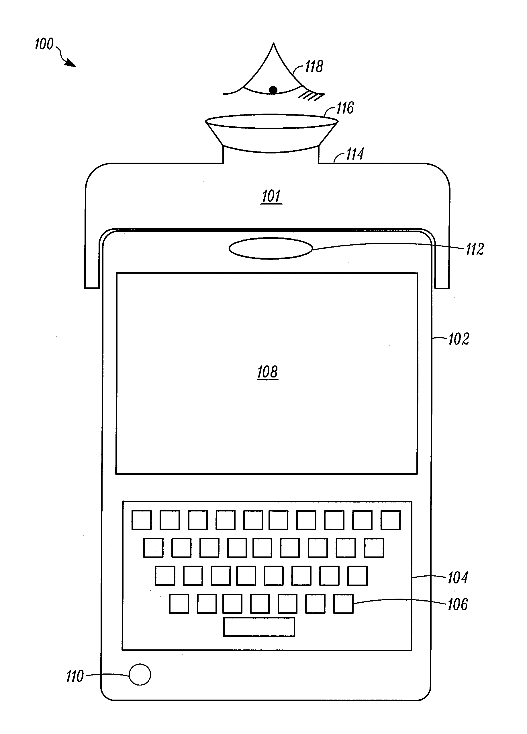
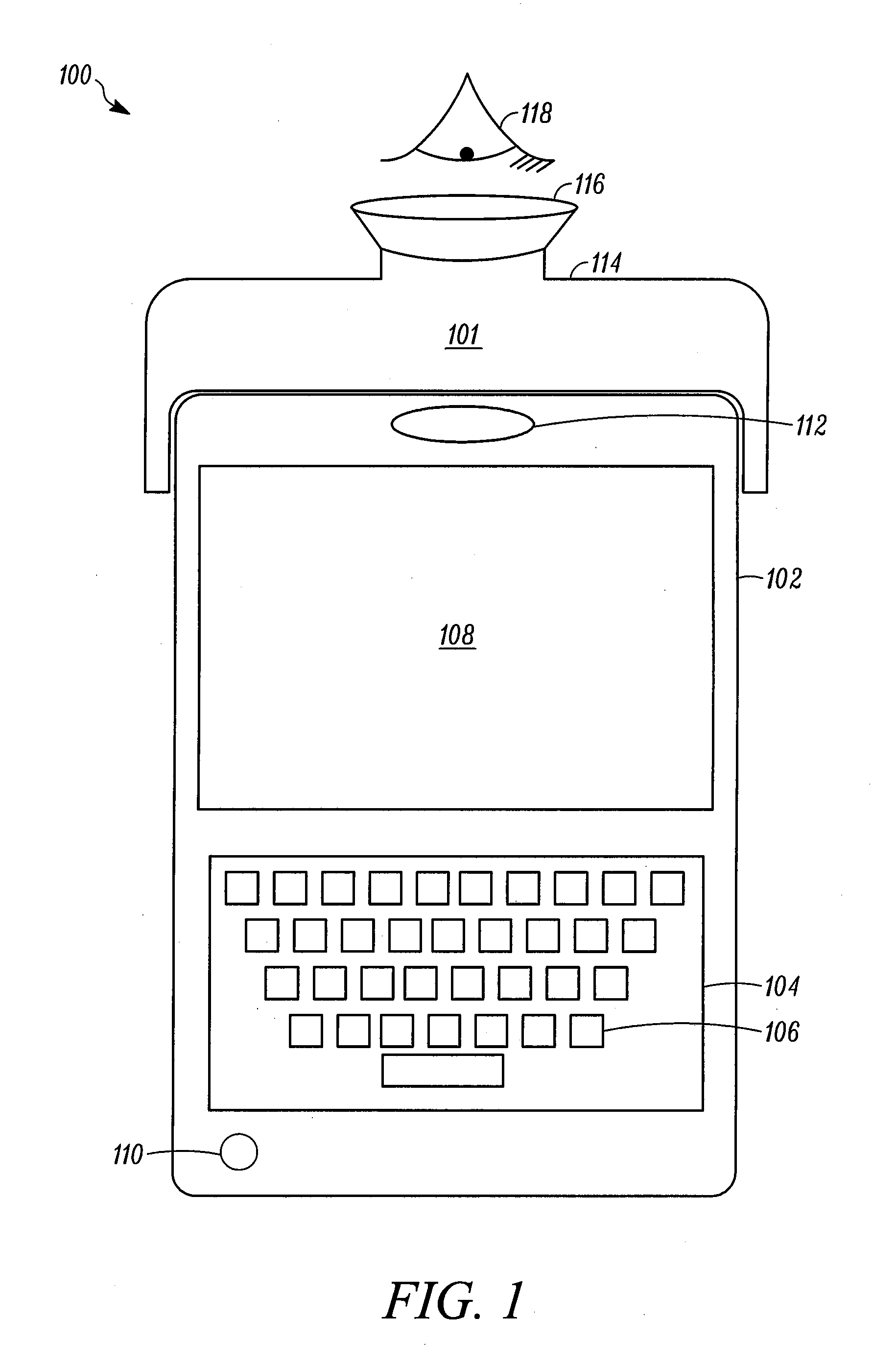
Portable device having a virtual display
a virtual display and portable technology, applied in the direction of electrical apparatus construction details, electrical apparatus casings/cabinets/drawers, instruments, etc., can solve the problem that small displays are not ideal for viewing large images or documents
- Summary
- Abstract
- Description
- Claims
- Application Information
AI Technical Summary
Benefits of technology
Problems solved by technology
Method used
Image

Examples
Embodiment Construction
[0019]The following detailed description is merely illustrative in nature and is not intended to limit the invention or the application and uses of the invention. Furthermore, there is no intention to be bound by any express or implied theory presented in the preceding technical field, background, brief summary or the following detailed description. For the purposes of conciseness, many conventional techniques and principles related to conventional image-based capture, need not, and are not, described in detail herein.
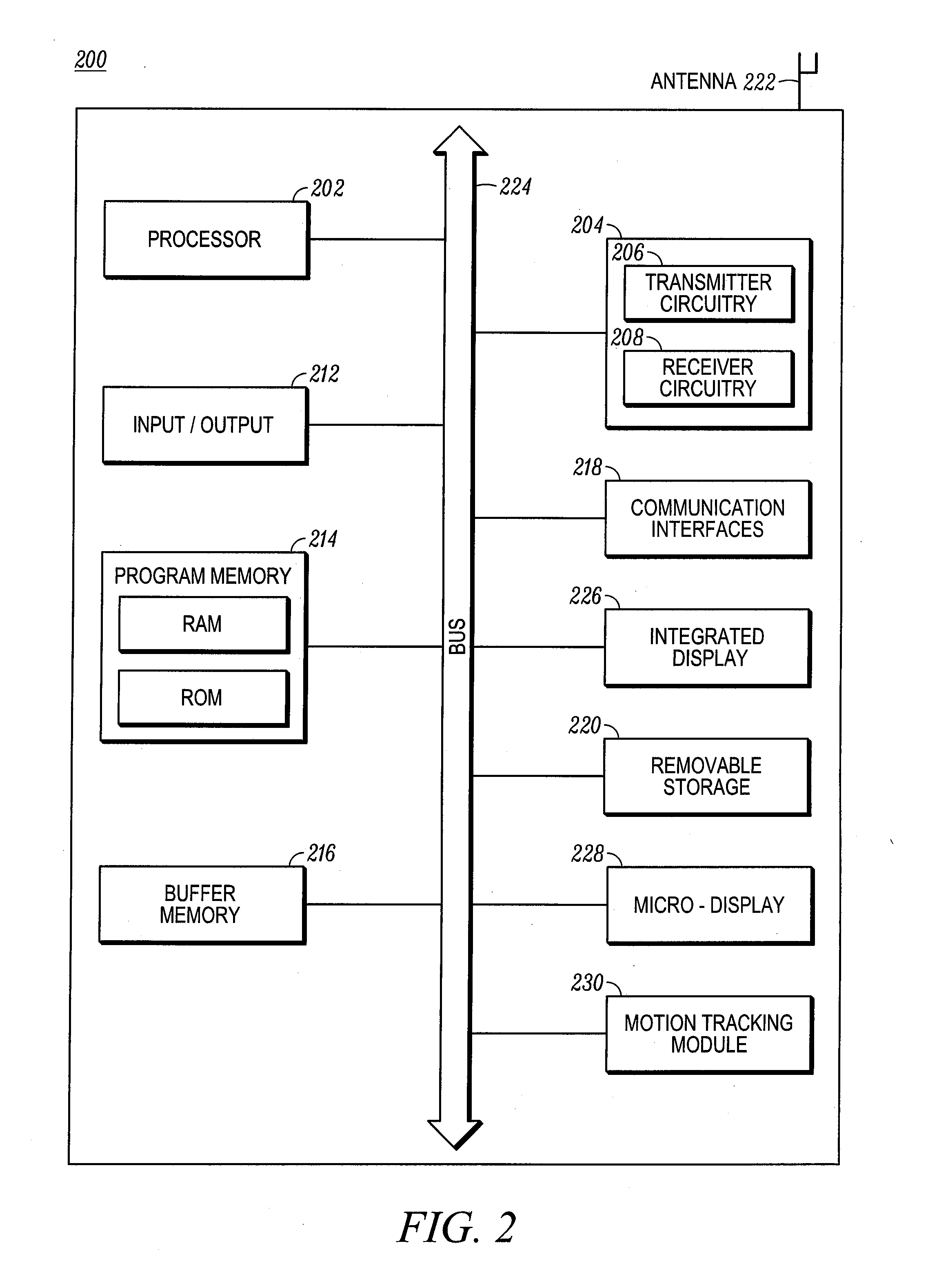
[0020]Techniques and technologies may be described herein in terms of functional and / or logical block components and various processing steps. It should be appreciated that such block components may be realized by any number of hardware, software, and / or firmware components configured to perform the specified functions. For example, an embodiment of a system or a component may employ various integrated circuit components, e.g., memory elements, digital signal processin...
PUM
 Abstract
Description
Claims
Application Information