
Machine tool

a technology of machine tools and tools, applied in the field of machine tools, can solve the problems of unavoidable undesirable reduction in difficult for an unexperienced operator to achieve satisfactory suppression, etc., and achieve the effect of suppressing chatter vibrations, enhancing the yield of machined products accordingly, and reducing the number of vibrations

Active Publication Date: 2012-05-03
OKUMA CORP +1
View PDF7 Cites 16 Cited by
  • Summary
  • Abstract
  • Description
  • Claims
  • Application Information

AI Technical Summary

Benefits of technology

The present invention provides a machine tool with a chatter vibration suppressing mechanism. The machine tool includes a rotary shaft and a driving unit connected to the rotary shaft to cause the rotary shaft to rotate. The driving unit is regulated to change the rotation speed of the rotary shaft with a given amplitude and period. The machine tool also includes a display device and a parameter display control unit to allow the operator to change the parameters that affect the rotation speed, such as the amplitude, period, angular acceleration, torque, power, rate of change, and mean rotation speed. This machine tool can effectively suppress chatter vibrations, even if the operator is not very experienced, and can improve the quality of machined products.

Problems solved by technology

A machine tool in which a tool, for example, is rotated to cut a surface of a workpiece may have chatter vibrations produced during its cutting operation for some reasons such as a low rigidity of the tool, or the like.
With the existing method as mentioned above, it is very difficult for an unexperienced operator to achieve satisfactory suppression of chatter vibrations, and an undesirable reduction in the yields of machined products is unavoidable, as the case may be.

Method used


Image

  • Machine tool
  • Machine tool
  • Machine tool

Examples


Embodiment Construction

[0023]A machine tool according to one embodiment of the present invention will be described in detail with reference to the drawings.

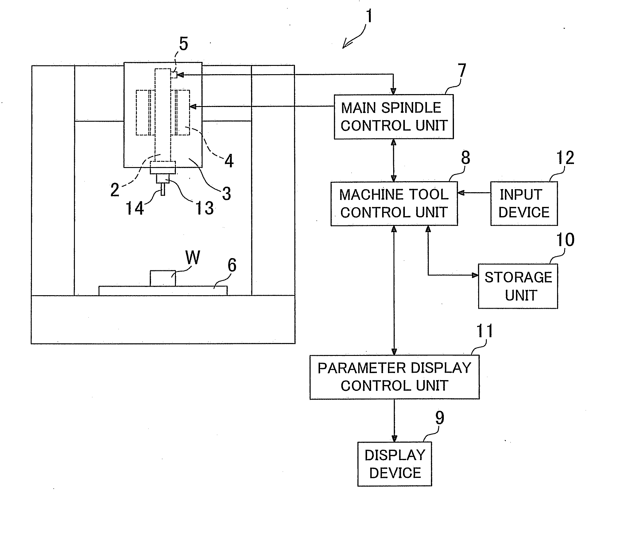
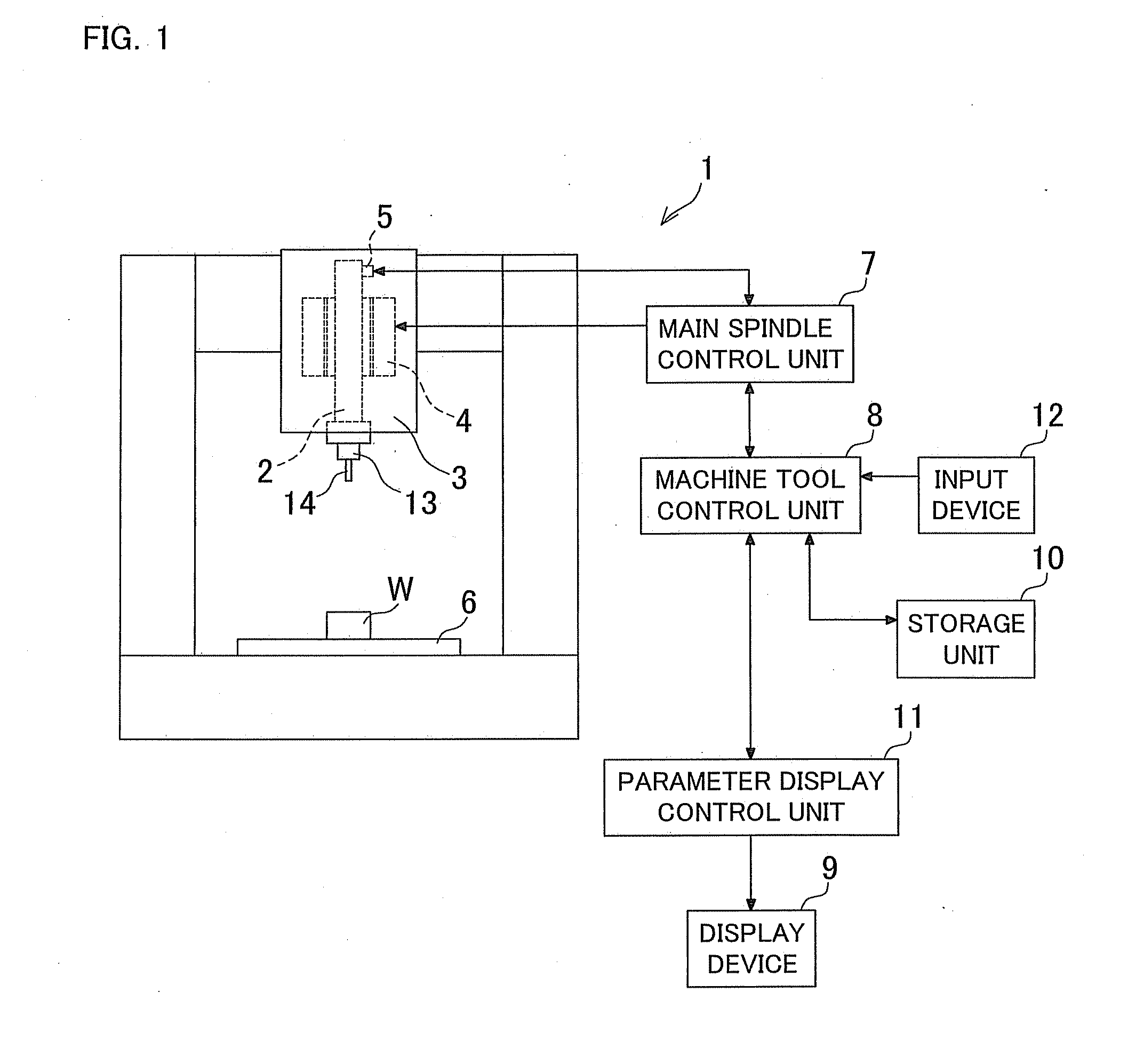
[0024]A machining center 1 as one example of a machine tool includes a main spindle 2 as an example of a rotary shaft to which a tool 14 is installable through a holder 13. The machining center 1 further includes a spindle head 3 in which the main spindle 2 and several other components such as a motor 4 and an encoder 5 are housed. The main spindle 2 is rotatably supported in the spindle head 3, and the motor 4 is configured to cause the main spindle 2 to rotate. The encoder 5 is configured to detect the rotation speed of the main spindle 2 or the motor 4. The machine tool 1 also includes a table 6 disposed in a position opposite to the spindle head 3 and configured to allow a workpiece W to be placed thereon.

[0025]A main spindle control unit 7 configured to control the rotation speed of the main spindle 2 and to regulate an amount of electric power su...


PUM

PropertyMeasurementUnit
rotation speedaaaaaaaaaa
mean rotation speedaaaaaaaaaa
torqueaaaaaaaaaa

Abstract

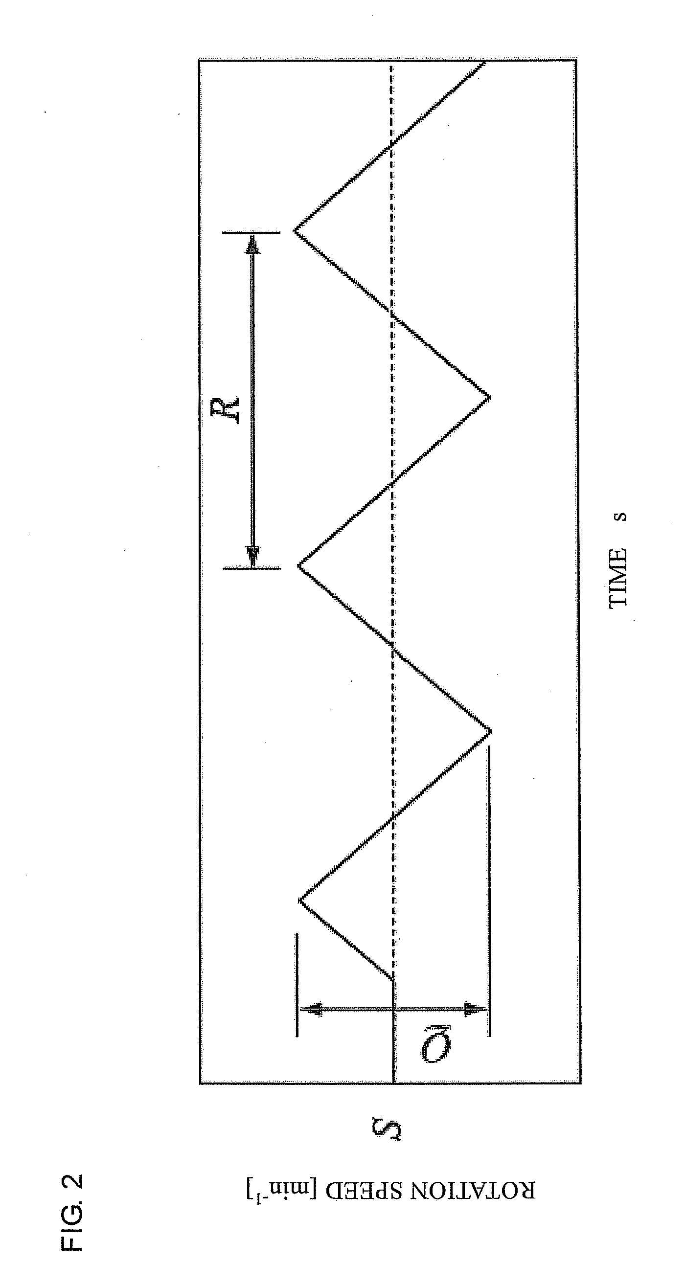
In a machine tool which includes a rotary shaft configured to allow a tool or a workpiece to be attached thereto, a driving unit for causing the rotary shaft to rotate is regulated to change a rotation speed of the rotary shaft in such a manner that the rotation speed oscillates with a given amplitude and a given period with respect to a given mean rotation speed, so that chatter vibrations can be suppressed. A parameter display control unit configured to cause a display device to display parameter information related to predetermined parameters for changing at least one of the mean rotation speed, the amplitude and the period is provided so that the parameters can be changed based upon the parameter information displayed in the display device.

Description

BACKGROUND OF INVENTION[0001]This application claims the benefit of Japanese Patent Application Number 2010-241137 filed on Oct. 27, 2010, the entirety of which is incorporated by reference.TECHNICAL FIELD[0002]The present invention relates generally to a machine tool which performs a machining operation on a workpiece with a tool while rotating the tool or the workpiece.BACKGROUND ART[0003]A machine tool in which a tool, for example, is rotated to cut a surface of a workpiece may have chatter vibrations produced during its cutting operation for some reasons such as a low rigidity of the tool, or the like. As a method for suppressing chatter vibrations, a method of periodically changing the rotation speed of the main spindle within a predetermined range (amplitude) is known in the art, as described in Japanese Patent Application Laid-Open Publications 49-105277 and 2000-126991.[0004]Conventionally, however, the amplitude and period of a periodical change (oscillation) in the rotatio...

Claims


Application Information

Patent Timeline
Patent Type & Authority Applications(United States)
IPC IPC(8): G05B19/18
CPCB23Q11/0032B23Q11/0039B23Q17/12Y10T409/307224Y10T409/306832Y10T409/304312B23Q15/08
Inventor NISHIMURA, KOHEIYOSHINO, KIYOSHIISHII, HAJIMUHAMAGUCHI, AKIHIDESUZUKI, NORIKAZUSHAMOTO, EIJI
Owner OKUMA CORP
Learn More