Electrostatic dust collector

Inactive Publication Date: 2012-05-10
CARL FREUDENBERG KG
View PDF4 Cites 0 Cited by
  • Summary
  • Abstract
  • Description
  • Claims
  • Application Information

AI Technical Summary

Benefits of technology

[0005]An object of the invention is to avoid the above-mentioned disadvantages, by providing a dust collector having a good efficiency and handling

Problems solved by technology

Due to the arrangement of the two electrodes in the grid-like mat, the previously known dust collector has the disadvantage that the highest field line density of the electric field, and thus the greatest polarization effect, is limited to the area between the two electrodes.
Such electrode configurations and geometries are not capabl

Method used


Image

  • Electrostatic dust collector
  • Electrostatic dust collector
  • Electrostatic dust collector

Examples


Example

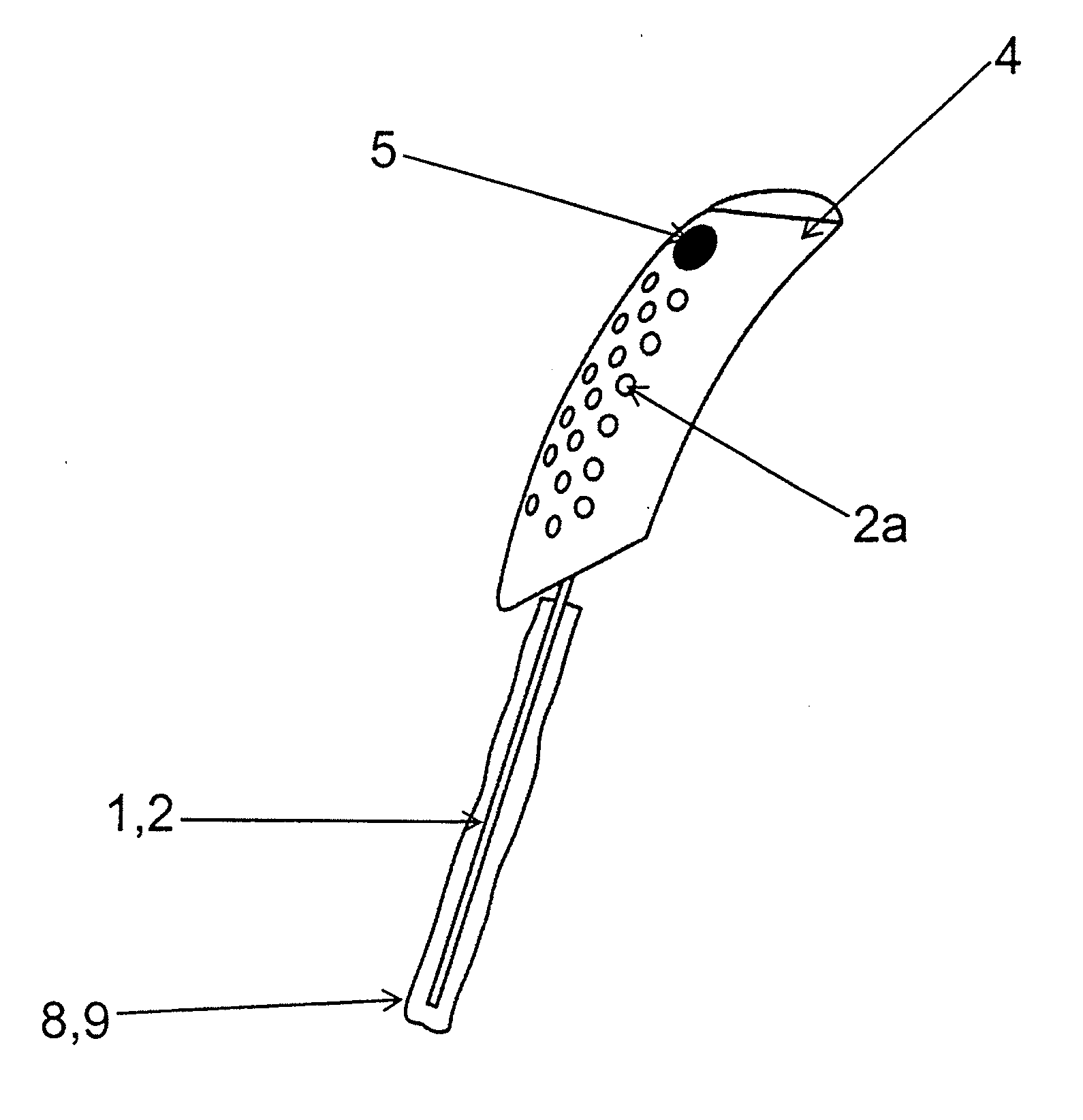
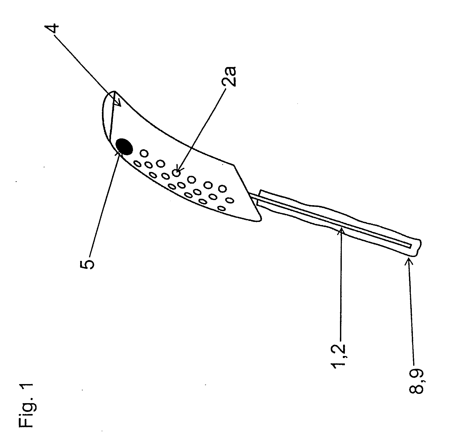
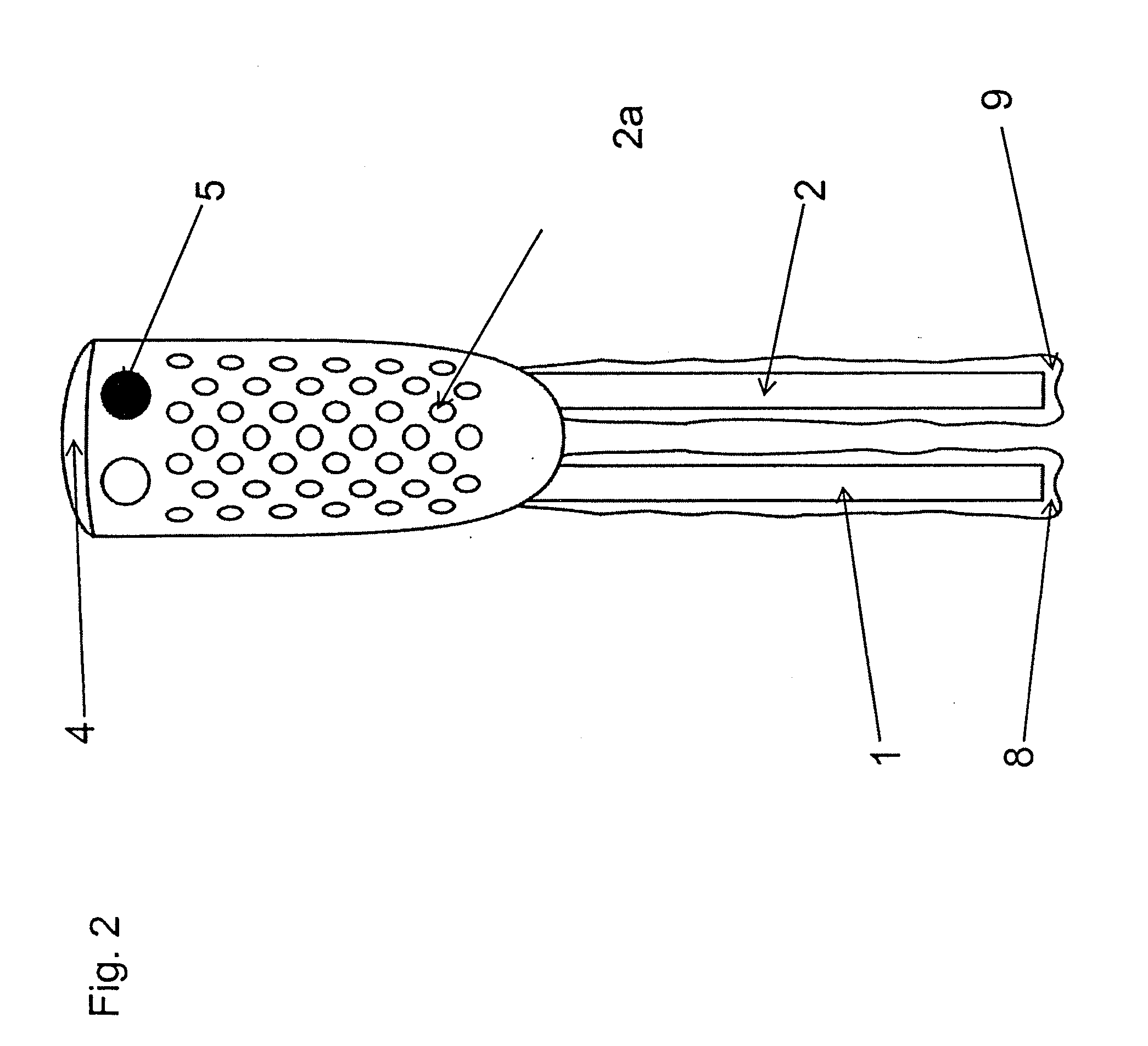
[0034]FIGS. 1-4 show two embodiments of an electrostatic dust collector, each of which includes a handle 4 and a dust collection device that is mounted on the handle 4. The dust collection device is formed by a first electrode 1 and a second electrode 2, which are completely enclosed in the illustrated embodiments by a sack-like dust cloth 8, 9. The dust cloth 8, 9 can consist entirely or partially of microfibers. The ground 2a of the dust collector is integrated into the handle 4. The voltage source 3 is arranged inside the handle 4 and protectively enclosed by the handle 4. The voltage source 3 is understood within the scope of the present invention to mean a device supplied by a battery or storage battery that generates voltages with a high arithmetic mean value. In the exemplary embodiment, the input voltage (battery voltage) is 3 V and the arithmetic mean value of the high voltage is ±5 kV.

[0035]To guarantee optimal dust collection and prevent an unpleasant charging of the user...


PUM


Abstract

Electrostatic dust collector comprising a first (1) and a second electrode (2), a voltage source (3) for applying a voltage between the two electrodes (1, 2), and a connection to ground (2a) is provided. The first electrode (1) and the second electrode (2) form a dust collection device, the first electrode (1) being positively charged and the second electrode (2) being negatively charged.

Description

CROSS-REFERENCED TO RELATED APPLICATION[0001]This patent is the national phase of PCT / EP2010 / 004233, filed Jul. 12, 2010, which claims the benefit of German Patent Application No. 10 2009 033 550.1, filed Jul. 16, 2009.FIELD OF THE INVENTION[0002]The invention relates to an electrostatic dust collector.BACKGROUND OF THE INVENTION[0003]An electrostatic dust mop is disclosed in US 2004 / 0163667 A1. The previously known dust collector includes a first and a second electrode and a voltage source for applying a voltage between the two electrodes.[0004]The known dust collector is constructed as a floor cleaning apparatus and has a grid-like mat, the two electrodes being components of the mat. The mat can be covered, for example, by a cleaning cloth. The voltage source is a battery arranged in the handle, for example, with the output voltage being converted into a high voltage. The area between the electrodes is electrically charged, the dust to be picked up having an opposite polarity with...

Claims


Application Information

Patent Timeline
IPC IPC(8): A47L13/40
CPCA47L13/38B08B6/00A47L13/40
Inventor GIBIS, KARL-LUDWIGKOSUB, MIKELEIBFRIED, THOMASHEROLD, CHRISTOPH
Owner CARL FREUDENBERG KG
Why Eureka
Try Eureka