Braking apparatus for a vehicle and vehicle comprising said braking apparatus

a technology for braking apparatus and vehicle, which is applied in the direction of braking system, gearing details, transportation and packaging, etc., can solve the problems of friction brake wear, friction brake wear, and inability to apply the braking force of friction brakes, so as to reduce the wear of friction brakes, reduce the damage to the transmission gear, and reduce the effect of friction brake wear

Active Publication Date: 2012-05-10
MERITOR TECH
View PDF6 Cites 9 Cited by
  • Summary
  • Abstract
  • Description
  • Claims
  • Application Information

AI Technical Summary

Benefits of technology

[0010]Thus, when the vehicle is travelling at relatively high speed and the brakes are applied relatively lightly, then under certain conditions (oil level around the transmission gear is high) the retarder is applied and under certain other conditions (oil level around the transmission gear is low) then only the friction brakes are applied. This minimizes damage to the transmission gear when the oil level around the transmission gear is low, but also reduces wear on the friction brakes when the oil level around the transmission gear is high.
[0011]If the oil level around the transmission gear is below the threshold level, the brake operating device may be further arranged to initiate an increase in the oil level around the transmission gear, and, when the oil level around the transmission gear is above the threshold level, the brake operating device is arranged to apply the at least one retarder. As the oil level is increased, the retarder can be applied in preference to the friction brake, and consequently wear of the friction brakes is further reduced.
[0012]In another example, if a degree of desired vehicle deceleration generated by the user is below a threshold degree, the brake operating device is arranged to initiate an increase in the oil level in the transmission gear on the brake operating device being operated by the user, and is further arranged to delay operation of the at least one retarder by a predetermined amount of time. As the brake operating device is arranged to initiate an increase in the oil level around the transmission gear, and as the brake operating device is arranged to delay operation of the retarder until a threshold time after operation of the brake operating device, the oil level around the transmission gear will always increase prior to the retarder being applied (unless it was already at a maximum level before the brake operating device was applied). Therefore, this aspect of the invention reduces wear of the transmission gear compared with a system in which the retarder is applied immediately that the brake operating device is operated by a user.
[0013]Preferably, the brake operating device is arranged to initiate an increase in the oil level around the transmission gear on the brake operation device being operated by a user only if the oil level around the transmission gear is below the threshold level. Therefore, unnecessary increases in the oil level, when the oil level is already sufficiently high, are avoided.
[0014]The braking apparatus may comprise a reservoir for storing oil, the reservoir being fluidly connected to the drive axle by a valve. The positioning of the reservoir in relation to the drive axle is such that, on opening of the valve, oil can flow from the reservoir into the drive axle under the influence of gravity, thereby increasing the oil level around the transmission gear. The oil level in the rear axle can therefore be increased in a simple manner.

Problems solved by technology

However, in some instances, for example in the case of a large truck attempting to decelerate while going downhill, friction brakes alone may not be enough to provide the required deceleration.
In particular, friction brakes may suffer from “brake fade” in which the braking force which the friction brakes are capable of applying decreases as result of repeated or prolonged use, often as a result of heat build up.
However, use of a retarder introduces torque into the transmission which can cause wear of the crown wheel and pinion, and wear of the differential.

Method used


Image

  • Braking apparatus for a vehicle and vehicle comprising said braking apparatus
  • Braking apparatus for a vehicle and vehicle comprising said braking apparatus
  • Braking apparatus for a vehicle and vehicle comprising said braking apparatus

Examples


Embodiment Construction

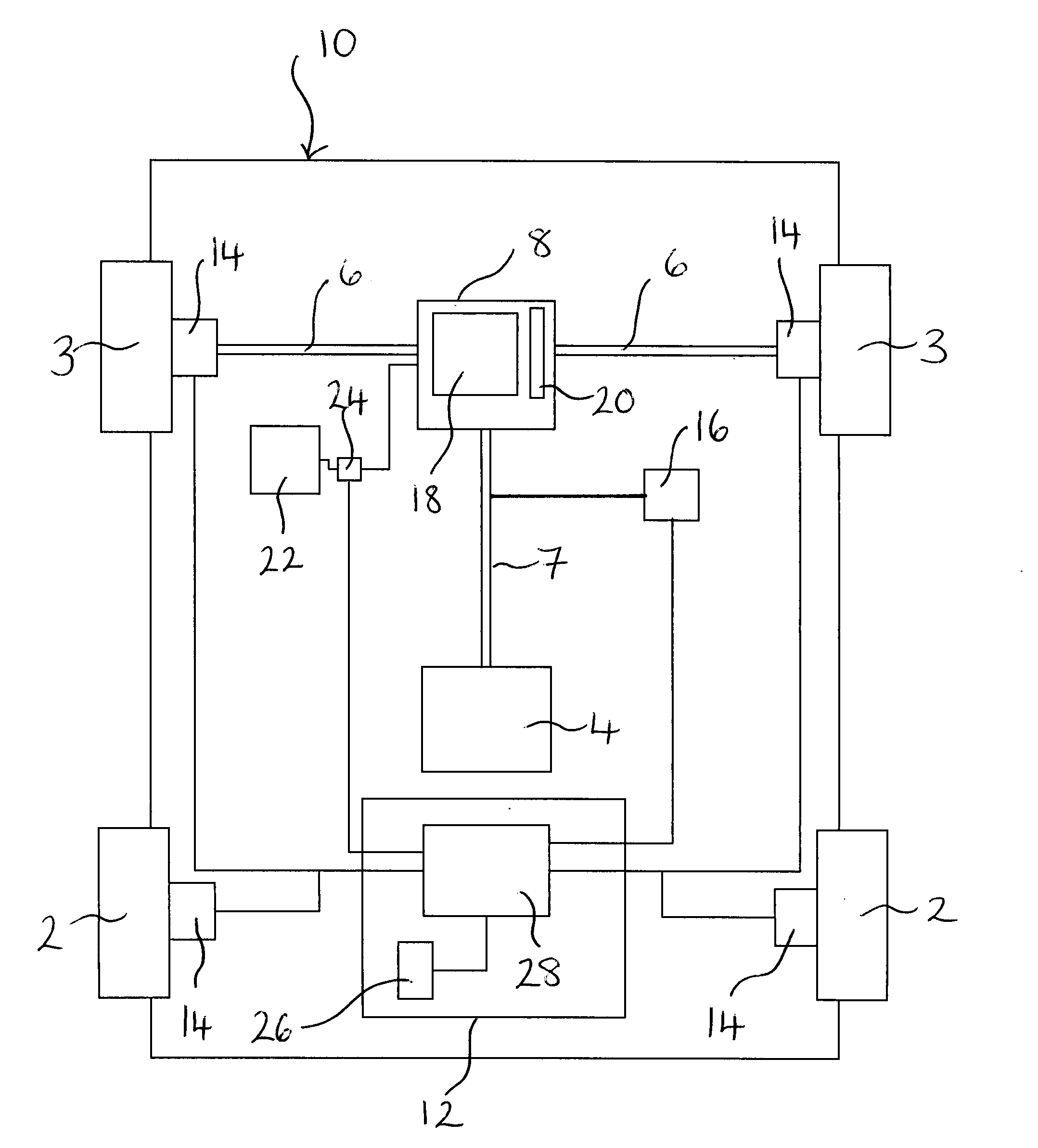
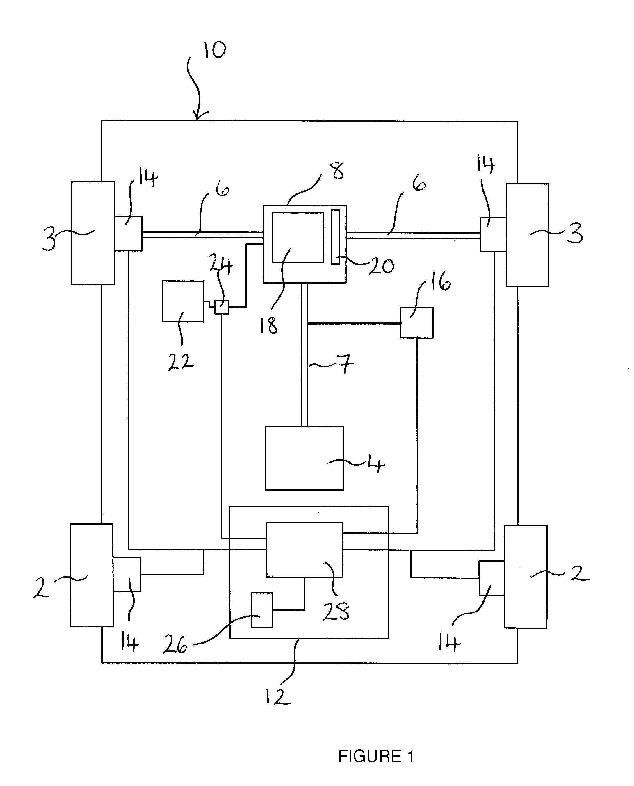
[0024]In the first embodiment, a vehicle 10 includes two front wheels 2, two rear wheels 3, and an engine 4. The two rear wheels 3 are linked by a rear axle 6, the rear axle 6 being a drive axle. The rear axle 6 includes a transmission 8 to transmit power from the engine 4 to the wheels 3. The engine 4 is connected to the transmission 8 via a drive shaft also known as a prop shaft 7. The transmission 8 includes a differential 18. The rear axle 6 includes oil for lubricating the gears of the transmission 8, including the differential 18, and a sensor 20 is provided in the rear axle 6 to determine oil level around the differential 18. The oil level around the differential 18 can be varied, and the rear axle 6 is fluidly connected to a reservoir 22, via a pump 24. The pump 24 can be used to pump oil from the reservoir 22 to the rear axle 6, and from the rear axle 6 to the reservoir 22. In use, the oil level in the rear axle 6 is generally minimized in situations in which the torque app...


PUM


Abstract

A braking apparatus for a vehicle, in particular a heavy goods vehicle, includes a drive axle having a transmission gear, such as a differential, around which an amount of oil for lubrication is variable. The brake apparatus further includes at least one friction brake and at least one retarder that is capable of operating to slow the vehicle through the transmission gear. The braking apparatus comprises a brake operating device for operating the at least one friction brake and the least one retarder, and a determining feature to determine an oil level around the transmission gear. The brake operating device, on operation by a user, is arranged to apply the retarder when the oil level around the transmission gear is above a threshold level, and, if the oil level is below the threshold level, the brake operating device is arranged to initiate an increase in the oil level around the transmission gear.

Description

RELATED APPLICATION[0001]This application claims priority to GB Patent Application No. 1018520.5, filed Nov. 3, 2010.TECHNICAL FIELD[0002]The present invention relates to a braking apparatus for a vehicle and a vehicle comprising said braking apparatus, in particular a vehicle including a rear axle having a transmission gear around which the amount of oil for lubrication is variable.BACKGROUND OF THE INVENTION[0003]One form of a known braking system is the use of friction brakes at the wheels of a vehicle. However, in some instances, for example in the case of a large truck attempting to decelerate while going downhill, friction brakes alone may not be enough to provide the required deceleration. In particular, friction brakes may suffer from “brake fade” in which the braking force which the friction brakes are capable of applying decreases as result of repeated or prolonged use, often as a result of heat build up. A known solution to this problem is to provide the vehicle with a re...

Claims


Application Information

Patent Timeline
Patent Type & Authority Applications(United States)
IPC IPC(8): B60T1/12A47H19/00
CPCB60T10/02F16H57/0447Y10T74/19991F16H57/0483F16H57/045
Inventor LEITER, RALFGIANONE, ROBERTOFRATELLI, MARCOBASSI, MARCOCESARI, CHIARASANTINATO, FABIOMAGNAGO, CLEMENTEHONIG, JONKAYYAR, KARTHIKPARK, JUCHIRLBONFA, CESARE
Owner MERITOR TECH
Why Eureka
Try Eureka