

Magnetic resonance imaging apparatus and magnetic resonance imaging method
- Summary
- Abstract
- Description
- Claims
- Application Information
AI Technical Summary
Benefits of technology
Problems solved by technology
Method used
Image

Examples
first embodiment
[0033]Hereinafter, a first embodiment to which the invention is applied will be described. Hereinafter, in all drawings for explaining the embodiments of the invention, the same reference numerals are given to elements with the same functions, and repeated explanation thereof will be omitted.
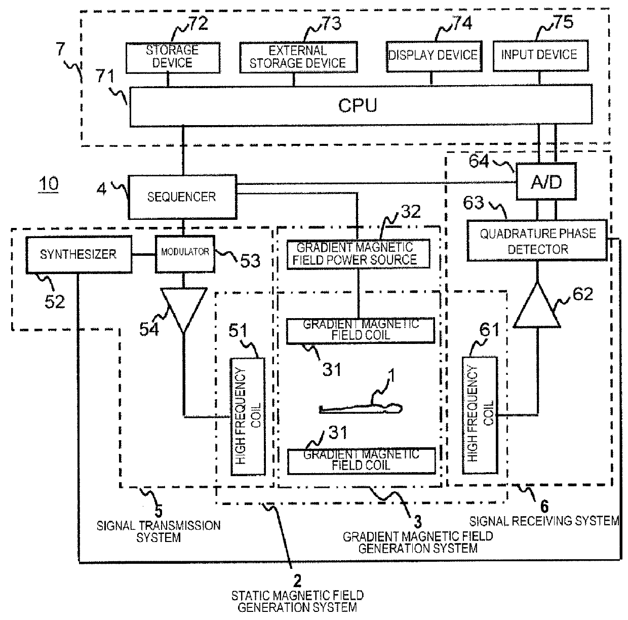
[0034]FIG. 1 is a block diagram showing the entire configuration in an example of an MRI apparatus 10 of the present embodiment. This MRI apparatus 10 acquires a tomographic image of an object 1 using an NMR phenomenon. As shown in FIG. 1, the MRI apparatus 10 includes a static magnetic field generation system 2, a gradient magnetic field generation system 3, a sequencer 4, a signal transmission system 5, a signal receiving system 6, and an information processing system 7.
[0035]The static magnetic field generation system 2 generates a uniform static magnetic field in the space around the object 1 in the body axis direction or a direction perpendicular to the body axis. The static magnetic field ...
second embodiment
[0076]Hereinafter, a second embodiment to which the invention is applied will be described. An MRI apparatus of the present embodiment is basically the same as that in the first embodiment. In addition, also in the present embodiment, the image quality is improved without lowering imaging efficiency while maintaining the features of non-Cartesian sampling as in the first embodiment. In the present embodiment, a function of correcting a data mismatch occurring between the shots is provided. Hereinafter, the present embodiment will be described focusing on the different configuration from the first embodiment.
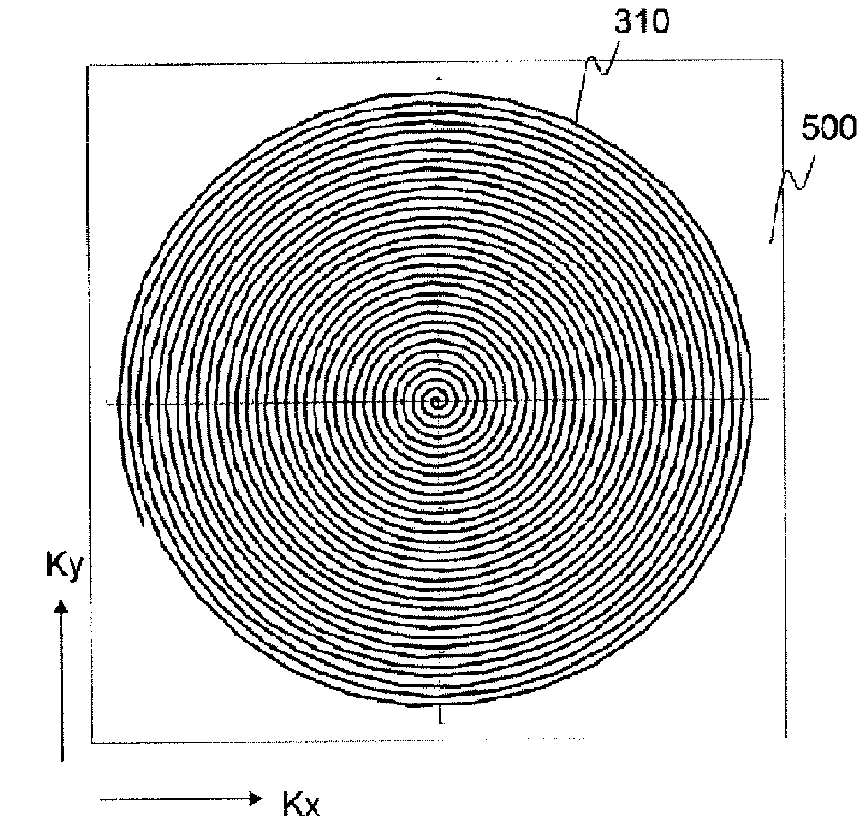
[0077]FIG. 7 is a view for explaining a read gradient magnetic field waveform of the sampling method of the present embodiment and a trajectory of the measurement space based on the read gradient magnetic field waveform. Basically, the sampling method of the present embodiment is also based on the spiral method in the same manner as in the first embodiment. The sampling method of...
third embodiment
[0092]Hereinafter, a third embodiment to which the invention is applied will be described. An MRI apparatus of the present embodiment is basically the same as that of each of the embodiments described above. In the present embodiment, a sampling method based on the data collection sequence part of the first or second embodiment is applied to the multi-echo method.
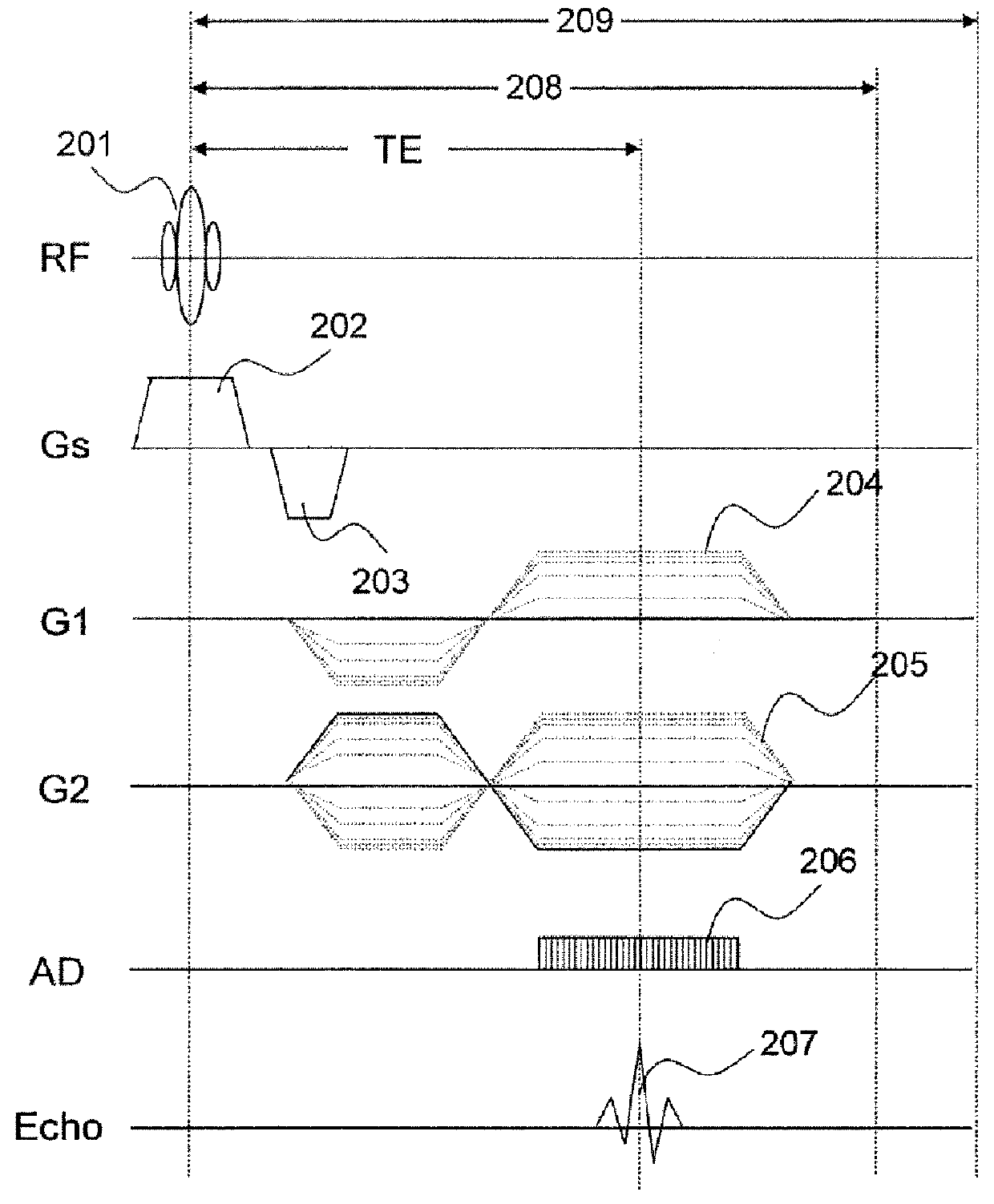
[0093]FIG. 9 is a pulse sequence when the sampling method of the present embodiment is applied to the multi-echo method. In this drawing, RF, Gs, G1, G2, AD, and echo indicate axes of an RF pulse, a slice gradient magnetic field, a read gradient magnetic field in a first direction, a read gradient magnetic field in a second direction, A / D conversion, and an echo signal, respectively. In addition, 801 is an RF pulse for excitation, 802 is a slice selection gradient magnetic field pulse, and 803 is a slice re-phase gradient magnetic field pulse.
[0094]Here, a pulse sequence in the case of a multi-echo method of 4 echoes of a s...
PUM
 Abstract
Description
Claims
Application Information