Method and apparatus for determining tire condition and location

a technology of condition and location, applied in the direction of tire measurement, vehicle tyre testing, vehicle components, etc., can solve the problem of waste of energy of tire-based sensors

Inactive Publication Date: 2012-05-10
TRW AUTOMOTIVE US LLC
View PDF5 Cites 71 Cited by
  • Summary
  • Abstract
  • Description
  • Claims
  • Application Information

AI Technical Summary

Problems solved by technology

The transmission of the tire rotation values each transmission of tire condition information results in wasted energy of the tire-based sensor which may be powered by a battery since the transmitted RF signal has to have at least two information portions, i.e., tire rotation information and tire condition information, for location allocation.

Method used


Image

  • Method and apparatus for determining tire condition and location
  • Method and apparatus for determining tire condition and location
  • Method and apparatus for determining tire condition and location

Examples


Embodiment Construction

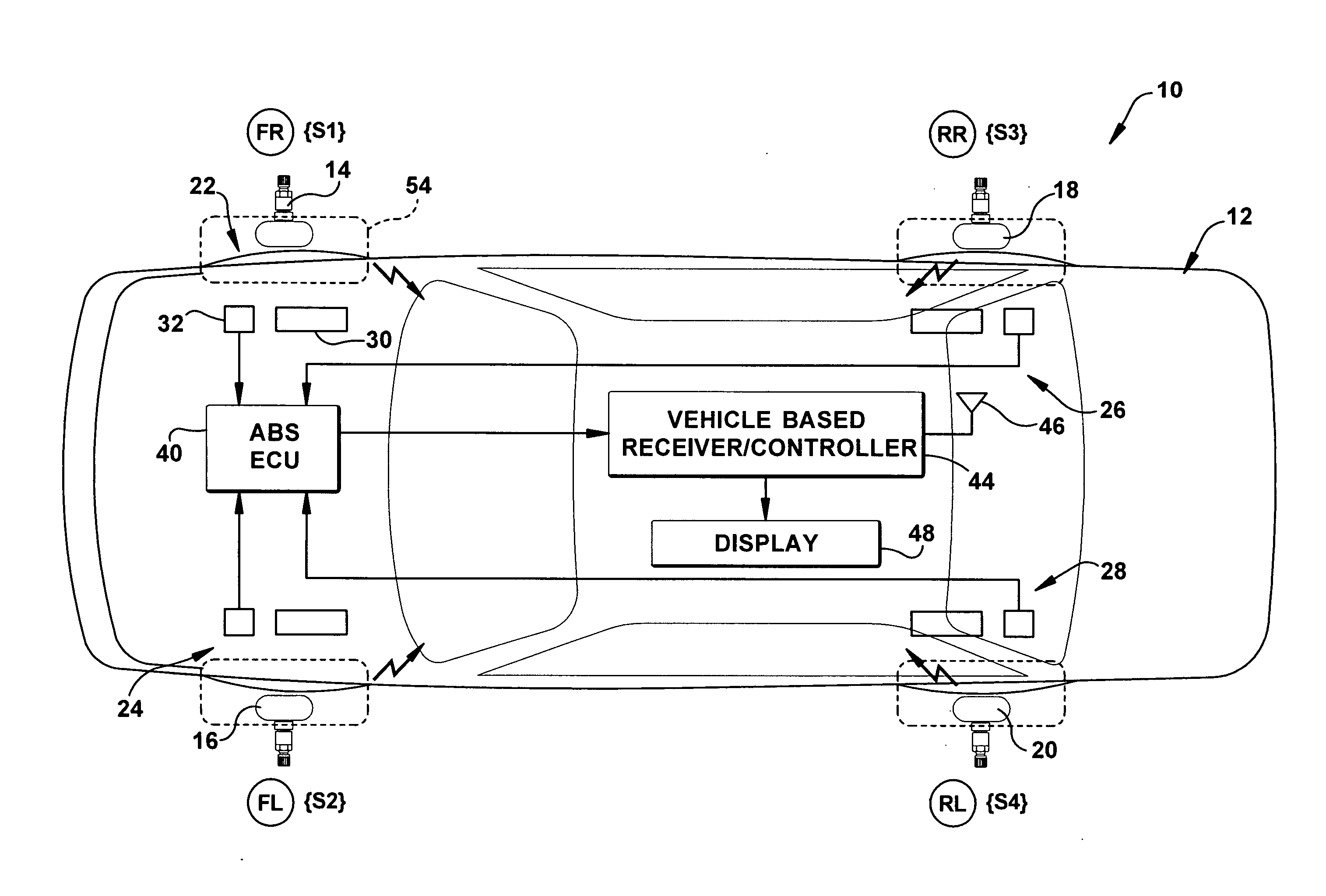
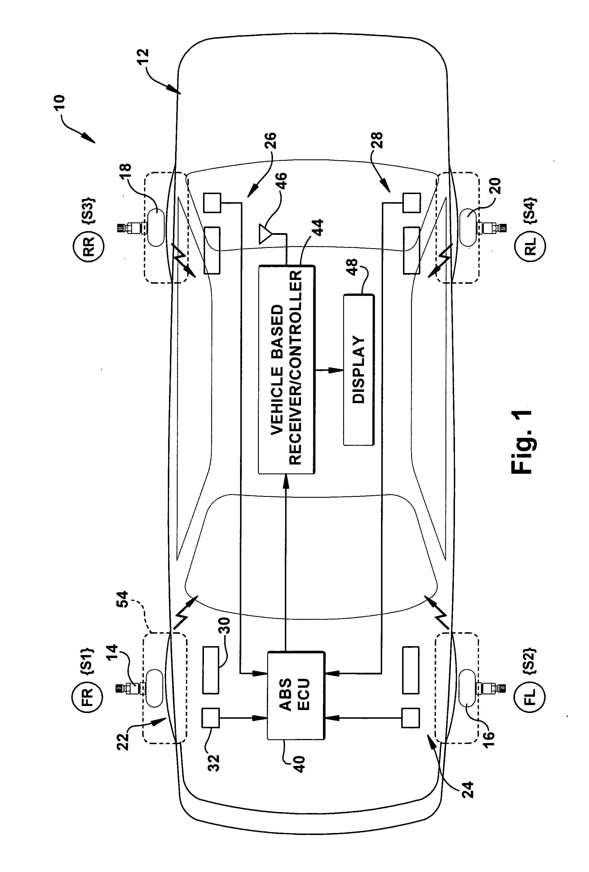
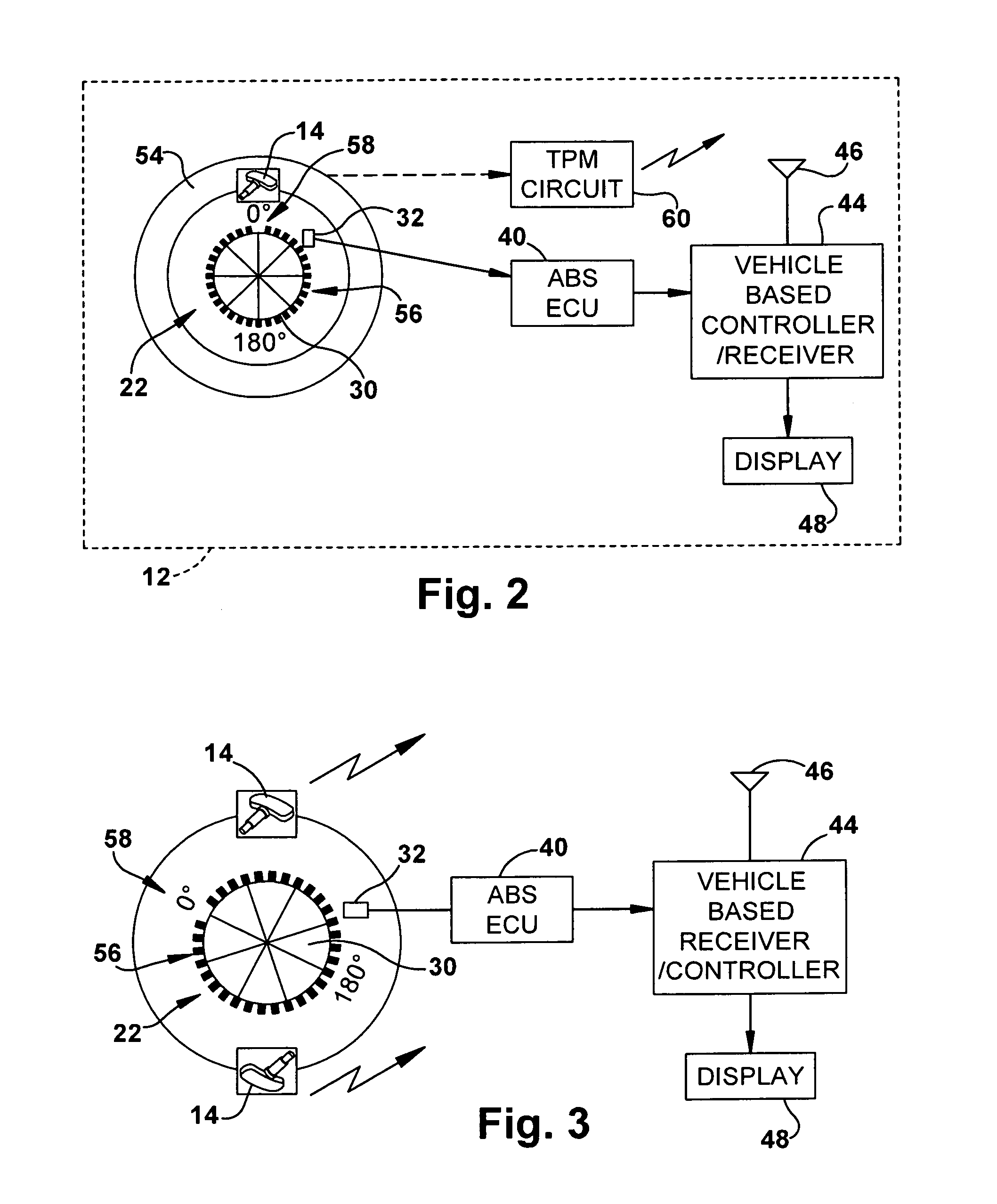
[0016]Referring to FIG. 1, a tire pressure monitoring (“TPM”) system 10, made in accordance with an example embodiment of the present invention, is shown mounted on a vehicle 12. The TPM system 10 includes a plurality of sensors 14 (“S1”), 16 (“S2”), 18 (“S3”), and 20 (“S4”) located at each of the four corners front right (“FR”), front left (“FL”), rear right (“RR”), and rear left (“RL”), respectively, of the vehicle 12. It should be understood that the sensors 14, 16, 18, and 20 are mounted in their associated tires in any of several known arrangements. For example, each of the TPM sensors can be mounted as part of the valve stem assembly, can be mounted in a separate housing and attached to the wheel rim, or to the side of the tire itself. Each of the sensors 14, 16, 18, and 20 include a sensor for sensing at least two predetermined angular positions of the tire during tire rotation and a sensor for sensing at least one condition of the tire, such as pressure and / or temperature. T...


PUM


Abstract

An apparatus (10) determines a tire condition and location on a vehicle (12) including a tire-based sensing unit (14), a plurality of tires (54) on the vehicle having an associated tire-based sensing unit, each tire-based sensing unit (14) including, a first tire rotation sensor (66) mounted for rotation with the tire (54) and for providing a first tire rotation signal (80) each time the tire passes one of at least two predetermined rotational positions during tire rotation, a tire condition sensor (82) for sensing a tire condition and for providing a tire condition signal indicative thereof and an unique tire identification indicator, a transmitter (86) for transmitting the tire condition signal and the unique tire identification indicator, and a controller for controlling the transmitter so that the transmission of the tire condition signal and the unique tire identification indicator occurs when the first tire rotation signal indicates the tire has reached one of the at least two predetermined rotational positions during tire rotation. The apparatus further includes a second tire rotation sensor (22) mounted external of the tire for sensing tire rotation and for providing a second tire rotation signal indicative of incremental angular position of the tire relative to a reference. A vehicle-based receiver (44) receives the transmitted tire condition signal, the unique tire identification indicator, and the second tire rotation signal and correlates reception of the tire condition signal with the second tire rotation signal so as to associate the unique tire identification indicator with a particular tire location on the vehicle.

Description

TECHNICAL FIELD[0001]The present invention relates to a method and apparatus for determining a tire condition and location on a vehicle in a tire pressure monitoring system.BACKGROUND[0002]Systems for sensing tire conditions and displaying sensed tire condition information to a vehicle occupant are known. Often, such systems are known as tire pressure monitoring (“TPM”) systems even though the system may sense tire conditions in addition to pressure, such as tire temperature. Such TPM systems include a tire-based sensor assembly that senses, for example, the air pressure and temperature inside its associated tire and transmits the sensed tire condition information to a vehicle-based receiver, i.e., a receiver mounted in the vehicle. The transmitted sensed tire condition signal may be a coded radio frequency (“RF”) signal. The vehicle-based receiver is connected to a display located in the vehicle cabin so as to display, for example, a warning signal to the vehicle operator when an u...

Claims


Application Information

Patent Timeline
Patent Type & Authority Applications(United States)
IPC IPC(8): B60C23/00
CPCB60C23/0416B60C23/0489B60C23/0488B60C23/0459B60C23/04B60C23/06B60C23/20G01M17/02
Inventor HANNON, TIMOTHY MICHAEL
Owner TRW AUTOMOTIVE US LLC
Why Eureka
Try Eureka