
Method for communicating in a mobile network

a mobile network and communication method technology, applied in the direction of payload allocation, transmission path sub-channel allocation, digital transmission, etc., can solve the problems of prohibitive processing complexity, limit the availability of suitable aggregations, and reduce the search space of control channel schemes

Active Publication Date: 2012-05-10
KONINKLJIJKE PHILIPS NV
View PDF28 Cites 7 Cited by
  • Summary
  • Abstract
  • Description
  • Claims
  • Application Information

AI Technical Summary

Benefits of technology

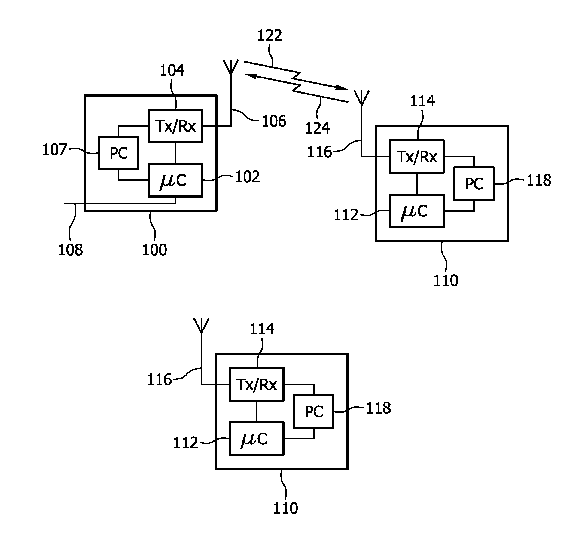
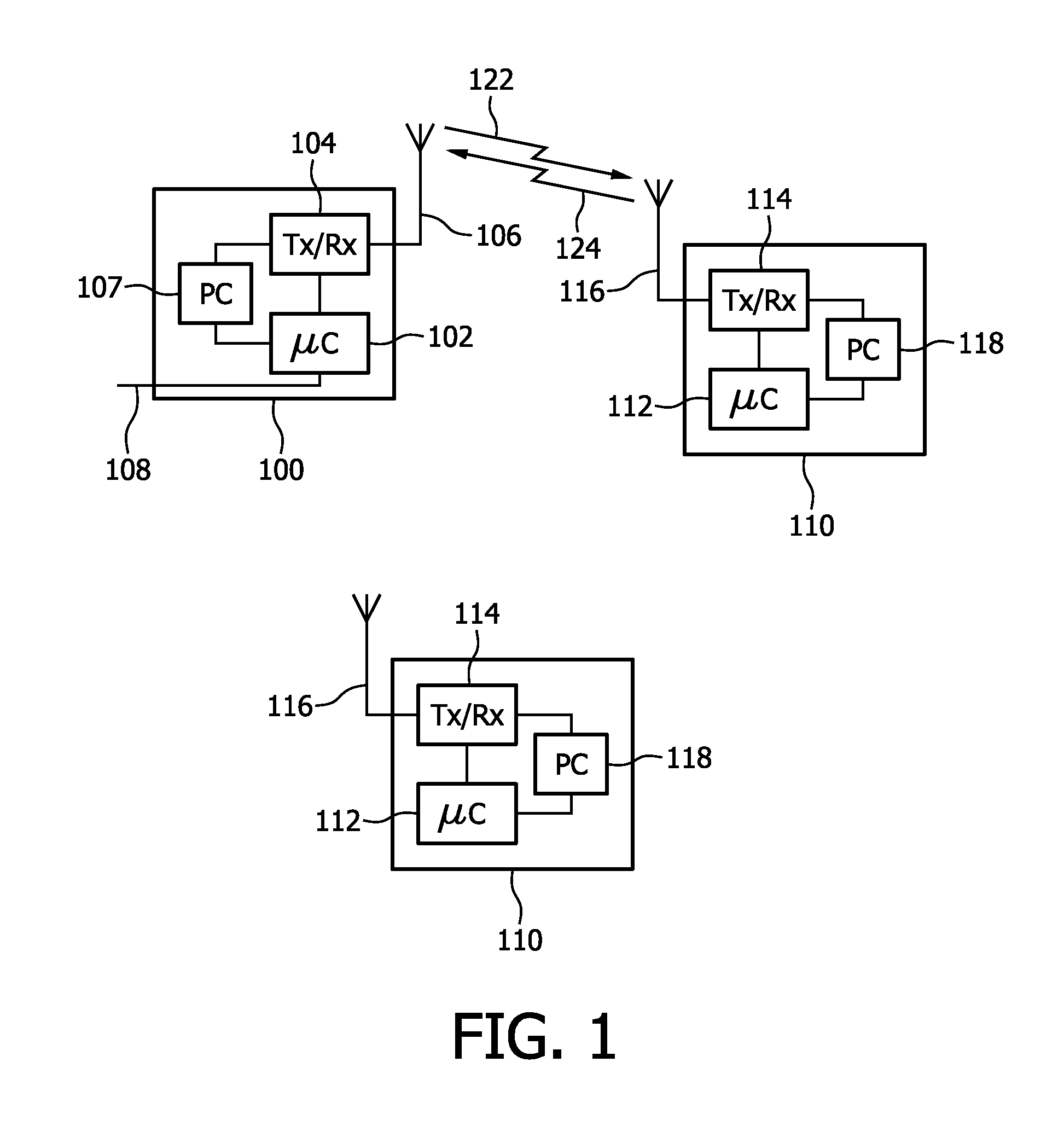
The invention proposes a method for communication between a primary station and multiple secondary stations. The primary station provides multiple resource sets and configures a secondary station to search for a control channel on one of the resource sets. The secondary station then deducts from the search space used for transmitting the control message an indication of the resource set in which the allocated resource is located. This allows the secondary station to determine the location of the allocated resource without needing additional signalling. The invention also provides a method for improving the control channel scheme with search spaces without increasing signaling overhead.

Problems solved by technology

However, if the CCE space is large the processing complexity is prohibitive.
However, restricting the search spaces to reduce processing complexity limits the availability of suitable aggregations for different conditions as conditions vary.

Method used


Image

  • Method for communicating in a mobile network
  • Method for communicating in a mobile network

Examples


fourth embodiment

A fourth embodiment is like the second embodiment, but with 5 carriers in UL and 3 carriers in DL. The search space on the non-anchor carriers is modified compared with the search space on the anchor carrier (carrier 0) but more blind decodings per carrier are allowed than in the third embodiment. For example on one additional carrier (Carrier 1) we could have:

Indicated UL Indicated DL carriercarrier (for (for PDCCH with PDCCHPDDCH with DL resourcepositionUL grant)allocation)011122230341

On the other additional carrier (Carrier 2) we could have:

Indicated UL Indicated DL carriercarrier (for (for PDCCH with PDCCHPDDCH with DL resourcepositionUL grant)allocation)011122230342

third embodiment

A fifth embodiment is like the third embodiment but where in order to give more flexibility the mapping between PDCCH position and carrier depends on the aggregation level. For aggregation level 1 we could have

Indicated UL Indicated DL carriercarrier offset offset (for PDCCH PDCCH(for PDDCHwith DL resourcepositionwith UL grant)allocation)00+11+10

For aggregation level 2 we could have

Indicated UL Indicated DL carriercarrier offset offset (for PDCCH PDCCH(for PDDCHwith DL resourcepositionwith UL grant)allocation)0−1+21+2−1

Part of the configuration of the mapping between PDDCH location may be fixed in the specification, for example as a default mapping in case no other mapping is signalled by higher layers.

Note that the PDCCH positions in the tables above are within the search space for a particular UE, which in general is located within a larger set of possible PDDCH locations

The invention may also be applied to indicate that the resources signalled in a PDCCH refer to another cell (wh...


PUM


Abstract

The present invention relates to a method or communicating between a primary station and a plurality of secondary stations, comprising the primary station providing a plurality of resource sets, the primary station configuring a secondary station to search for a control channel on at least one of a plurality of search spaces each corresponding to a resource set, wherein at least part of one of the search spaces is used to transmit a control message to a secondary station, the control message being indicative of a resource allocated to the secondary station for transmitting to the primary station or receiving from the primary station data, and wherein the secondary station deduces from the part of the search space used for transmitting the control message an indication of the resource set from the plurality of resource sets within which the allocated resource is located.

Description

FIELD OF THE INVENTION[0001]The present invention relates to a method for communicating in a network. More specifically, the present invention relates to communication between a primary station and a secondary station, in a telecommunication network, like a cellular telecommunication network (e.g. UMTS, UMTS LTE, GSM).BACKGROUND OF THE INVENTION[0002]In a mobile network, as e.g. UMTS LTE, the downlink control channel PDCCH (Physical Downlink Control Channel) carries information such as resource allocation for uplink or downlink transmission. A PDCCH message can use 1, 2, 4 or 8 Channel Control Elements (CCEs or resource elements)—referred to as CCE aggregation levels 1, 2, 4 or 8.[0003]A mobile station, like a UE in LTE, does not know in advance the location in CCE space of messages intended for it. In principle, the mobile station could attempt to blindly decode all the possible PDCCHs with different starting positions in the CCE space and thus receive any messages intended for tha...

Claims


Application Information

Patent Timeline
Patent Type & Authority Applications(United States)
IPC IPC(8): H04W72/04
CPCH04L5/0044H04W72/042H04L5/0092H04L5/0053H04W72/23H04W72/0446H04W72/0453H04W72/20H04W72/044
Inventor MOULSLEY, TIMOTHYCHIAU, CHOO CHIAPTESANOVIC, MILOS
Owner KONINKLJIJKE PHILIPS NV
Learn More