Medical Suction Clearing Apparatus

a technology of medical suction and clearing apparatus, which is applied in the field of medical suction clearing apparatus and surgical tools, can solve the problems of clogging the suction tube with tissue removal, affecting the patient's recovery, and wasting every minute of wasted time, so as to prevent the loss of suction, quick clear an obstruction, and improve the fluid flow

Inactive Publication Date: 2012-05-17
ONTIUM
View PDF22 Cites 1 Cited by
  • Summary
  • Abstract
  • Description
  • Claims
  • Application Information

AI Technical Summary

Benefits of technology

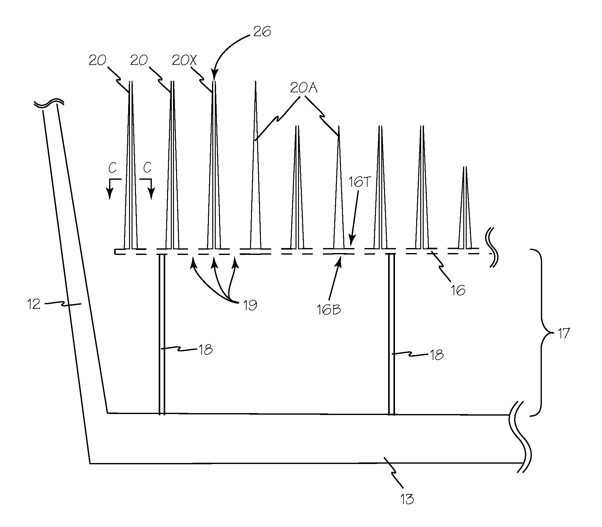
[0004]The devices and methods described below provide for a cleaning apparatus to be provided for every procedure requiring suction to enable a surgeon to quickly clear an obstructed suction tool without surrendering the suction tool. A suction cleaning cup is an open top vessel containing clean saline or other suitable cleaning liquid. The cleaning cup includes generally planar cleaning plate that is spaced above the floor of the cup to create a fluid filled plenum between the cleaning plate and the floor of the cleaning cup. The cleaning plate is perforated to permit fluid flow from the plenum through the cleaning plate into a suction tool to prevent loss of suction while clearing an obstruction of the suction tool bore. The upper surface of the cleaning plate includes one or more areas with arrays of tapered cleaning bristles sized to extend inside the suction tool bore to mechanically clear the suction tool bore.
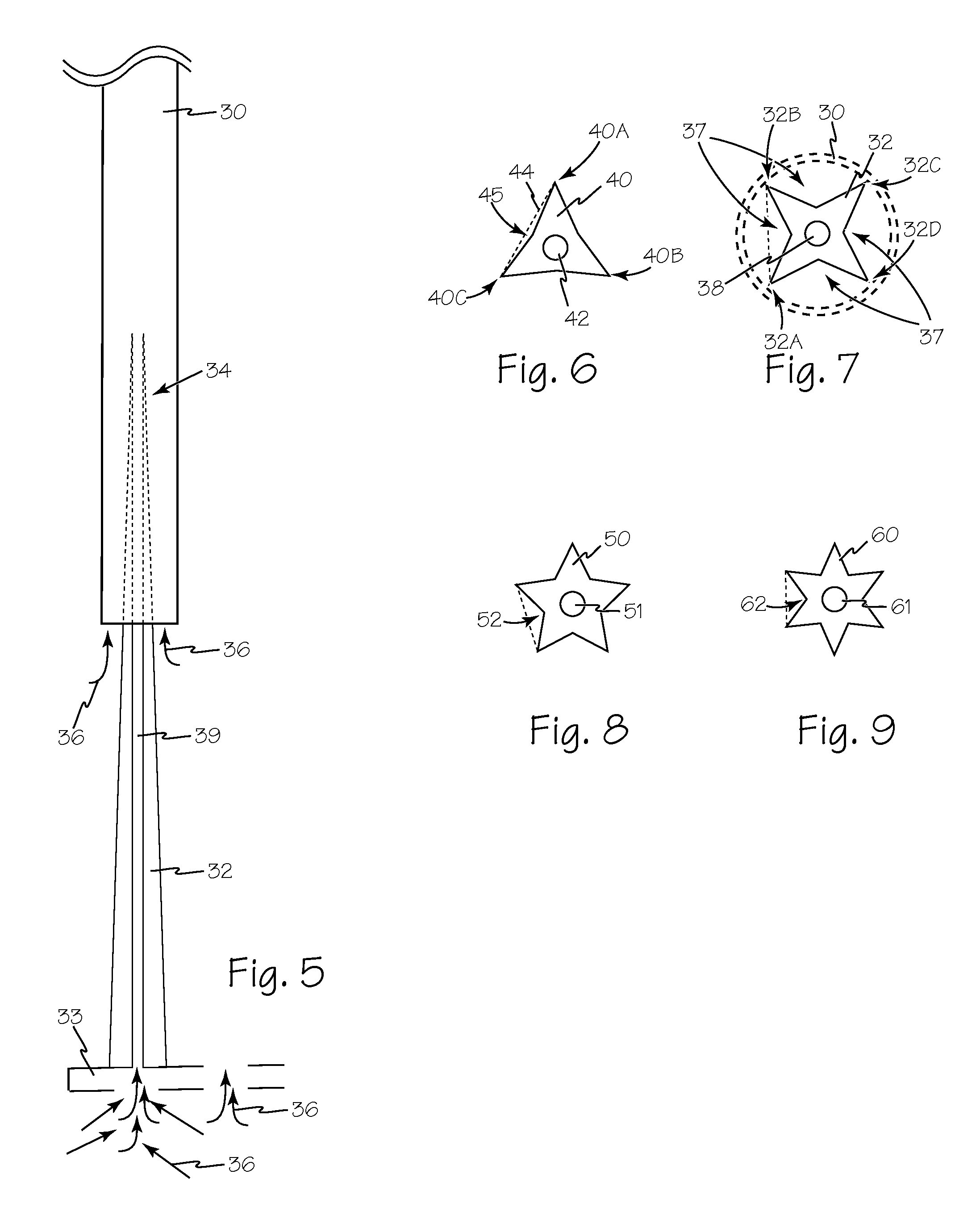
[0005]The tapered bristles are configured with a central channel to conduce fluid from the fluid plenum to the tip of the bristle. The tapered bristles also include longitudinal flutes which improve fluid flow between generally parallel vertex ridges. The improved fluid flow through the flutes helps clear obstructed suction tools.
[0006]The bristles may be arranged by height on the cleaning plate to form areas that will be readily identifiable to a medical professional seeking to clear an obstructed suction tool. For example, on a round cleaning plate the bristles may be arranged in concentric circles forming a bulls eye pattern enabling a user to readily identify suitable areas for clearing an obstructed suction tool.

Problems solved by technology

Surgical procedures are complicated, dangerous and expensive.
During surgery, the suction tube may become clogged with tissue being removed from the surgical site.
With surgery costs into the hundreds of dollars per minute, every minute wasted is expensive and potentially dangerous for the patient.

Method used


Image

  • Medical Suction Clearing Apparatus
  • Medical Suction Clearing Apparatus
  • Medical Suction Clearing Apparatus

Examples


Embodiment Construction

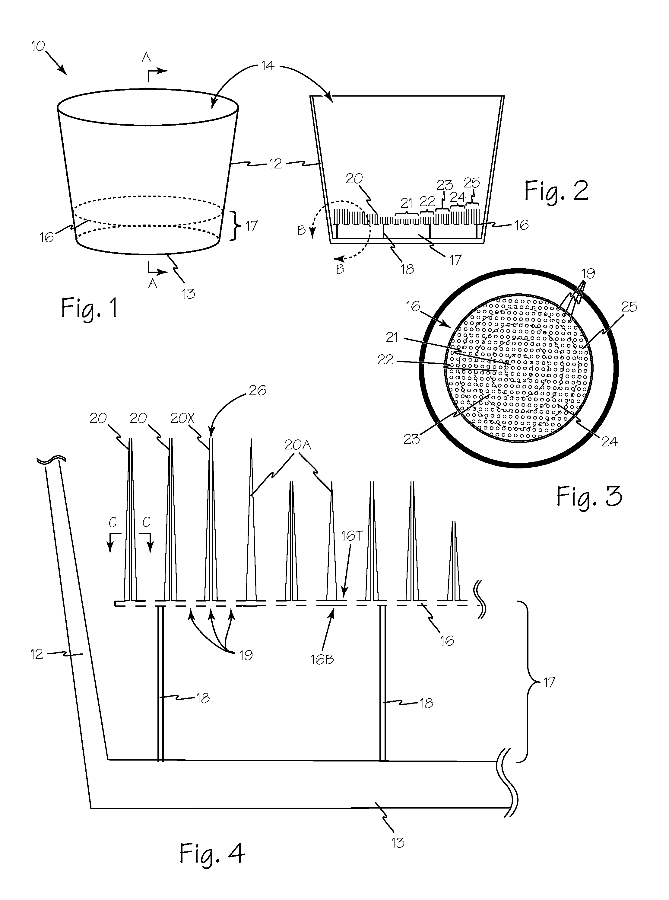
[0018]Suction cleaning cup 10 is illustrated in FIG. 1. Side wall such as wall 12 along with floor 13 define cleaning fluid volume 14. Cleaning cups such as cleaning cup 10 may adopt any suitable shape such as conical or frusto-conical to optimize the ratio of material to form the cup versus cleaning fluid volume. Cleaning plate 16 is located within cleaning fluid volume 14 and is oriented to form plenum 17 between cleaning plate 16 and cleaning cup floor 13.

[0019]Referring now to FIGS. 2, 3 and 4, cleaning plate 16 may be solid or perforated to permit fluid flow through the cleaning plate to prevent loss of suction and maintain fluid flow as a suction tool tip approaches the cleaning plate or engages the suction plate during cleaning. Plenum 17 is formed when cleaning plate 16 is maintained a suitable distance from floor 13 by one or more support legs such as support legs 18 and includes a suitable number of openings or perforations such as holes 19. A suitable number of tapered br...


PUM


Abstract

A suction cleaning apparatus is a generally cylindrical vessel for enclosing any suitable cleaning fluid such as water or saline solution. A generally planar cleaning plate with an upper and lower surface is supported a suitable distance from the cup floor by a plurality of legs forming a fluid plenum between the lower surface of the cleaning plate and the cup floor. The upper surface of the cleaning plated has a plurality of bristles extending from the upper surface for mechanically cleaning an obstructed suction tool. In use, an obstructed suction tool is inserted into the cleaning fluid and pushed into engaging the bristles. The bristles are sized such that one bristle extends into the obstructed suction tool to mechanically disengage the obstruction. The bristles may include a central channel for conducting cleaning fluid from the fluid plenum to the tip of the bristle increasing fluid flow into and obstructed suction tool to expedite clearing the obstruction. The cleaning plate may also be perforated to increase fluid flow around the tip of an obstructed suction tool when it is engaging the bristles.

Description

FIELD OF THE INVENTIONS[0001]The inventions described below relate to the field of surgical tools and more specifically to surgical tools for clearing obstructions in surgical suction devices.BACKGROUND OF THE INVENTIONS[0002]Surgical procedures are complicated, dangerous and expensive. The tools used by surgeons are selected to provide the greatest utility and efficiency to achieve optimal outcomes for the patient. A basic tool used in virtually every surgical procedure is suction which is implemented through a slender tube. During surgery, the suction tube may become clogged with tissue being removed from the surgical site. Once clogged, the suction apparatus requires a surgical assistant to clear the obstruction to enable the surgery to continue. With surgery costs into the hundreds of dollars per minute, every minute wasted is expensive and potentially dangerous for the patient.SUMMARY[0003]A suction cleaning apparatus as described below is a generally cylindrical vessel for enc...

Claims


Application Information

Patent Timeline
Patent Type & Authority Applications(United States)
IPC IPC(8): B08B9/00
CPCA61B19/34B08B9/00B08B1/00A61B90/70
Inventor BERRY, MARKLEWIS, KENNETH D.
Owner ONTIUM
Why Eureka
Try Eureka