On-board optical sensor cover and on-board optical sensor apparatus

Inactive Publication Date: 2012-05-17
DENSO CORP
View PDF3 Cites 149 Cited by
  • Summary
  • Abstract
  • Description
  • Claims
  • Application Information

AI Technical Summary

Benefits of technology

[0005]In view of the above, it is an object of the present invention is to provide an on-board optical sensor cover and an on-board optical sensor apparatus for suitably removing a foreign matter sti

Problems solved by technology

As a result, the cost an

Method used


Image

  • On-board optical sensor cover and on-board optical sensor apparatus
  • On-board optical sensor cover and on-board optical sensor apparatus
  • On-board optical sensor cover and on-board optical sensor apparatus

Examples


first embodiment

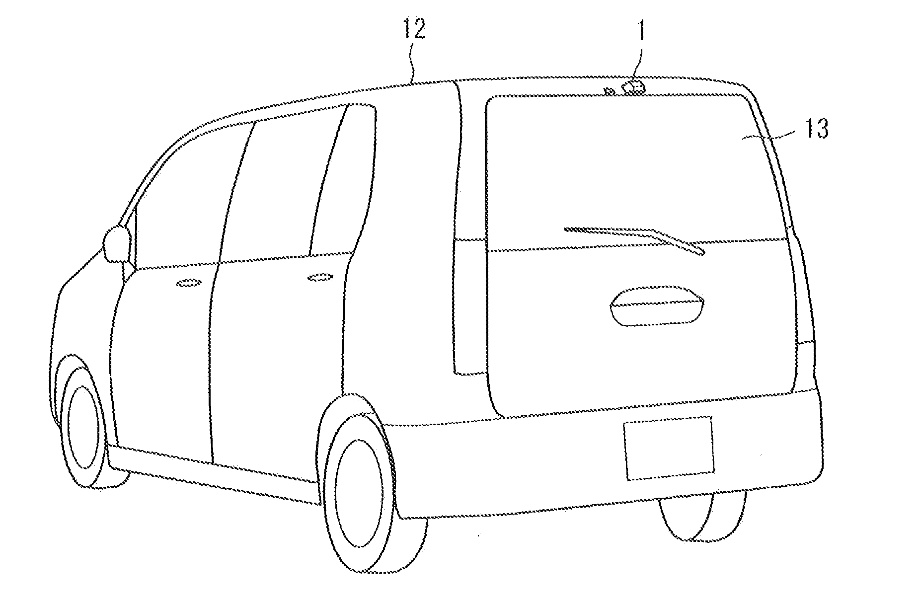
[0071]A first embodiment related to a camera embodying an optical sensor of the present invention is described below with reference to FIGS. 1A-5.

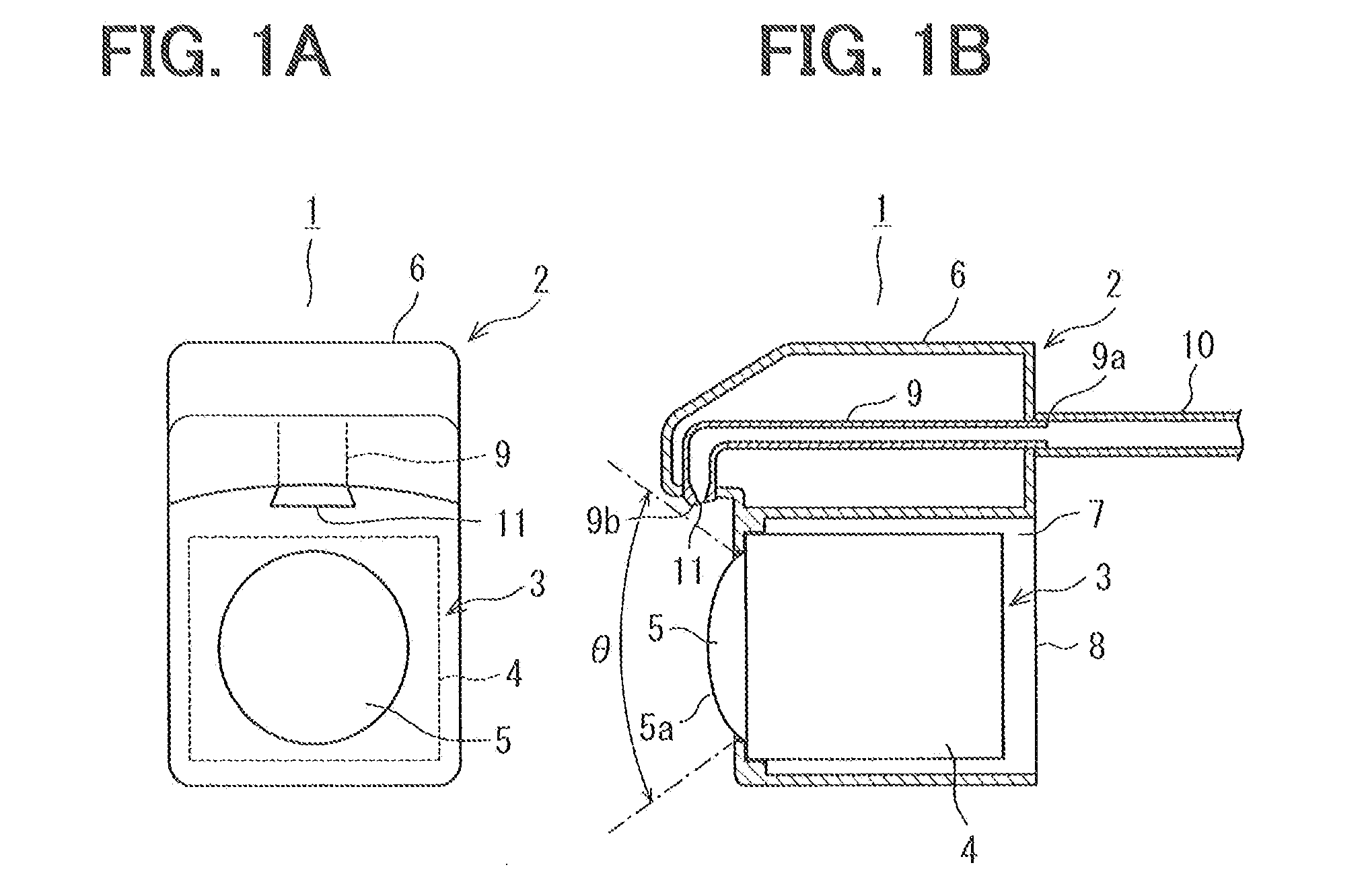
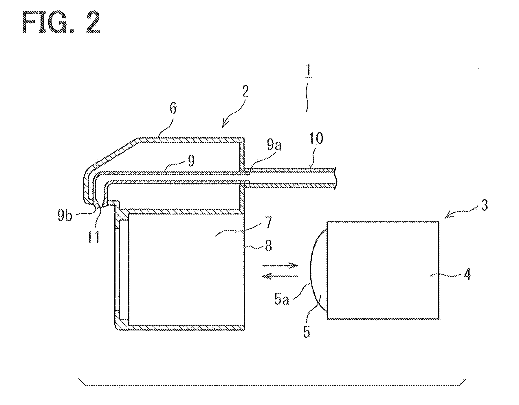
[0072]As shown in FIGS. 1A and 1B, an optical sensor unit 1 (an on-board optical sensor apparatus of the present invention) includes a camera cover 2 (an on-board optical sensor cover of the present invention) and a camera 3. The camera 3 is attached to the camera cover 2 in a detachable manner. In the camera 3, a lens 5 is located on a front side (a left side in FIG. 1B) of a casing 4, and a power supply line (not shown) and an image signal output line (not shown) are drawn from a rear side (a right side in FIG. 1B) of the casing 4. The power supply line is used to supply power to the camera 3. The image signal output line is used to output an image signal. The lens 5 is a fisheye lens and has a curved lens surface 5a that can take a wide-angle image.

[0073]In the camera cover 2, a holder 7 for holding the camera 3 is located in a casing 6...

second embodiment

[0081]A second embodiment of the present invention is described below with reference to FIGS. 6 and 7. The second embodiment differs from the first embodiment in the following points. In the first embodiment, the washing operation of the washer nozzle 9 is triggered when the washer switch 18 is operated by a user. That is, the washing operation of the washer nozzle 9 is manually performed. In the second embodiment, operating conditions include detection of the fact that the gear is shifted into a reverse position (detection of the fact that a gear of a vehicle is in a predetermined position in the present invention), detection of the fact that the IG switch is switched from an OFF state to an ON state (detection of the fact that activation of a vehicle is started in the present invention), and detection of the fact that the IG switch is switched from the ON state to the OFF state (detection of the fact that activation of a vehicle is ended in the present invention). The washing oper...

third embodiment

[0109]A third embodiment of the present invention is described below with reference to FIGS. 24A-27. The third embodiment differs from the first embodiment in the following points. As shown in FIGS. 24A and 24B, a heater 201 (an optical heating device and a nozzle heating device, which are integrally formed from the same member, in the present invention) and a wire (not shown) for supplying an electric current to the heater 201 are located in the casing 6. In the condition where the camera 3 is normally held in the holder 7, the heater 201 covers the entire side periphery of the lens 5 of the camera 3 and is in contact with a portion (near a curved portion in the present embodiment) of the washer nozzle 9 on the tip end 9b side. For example, the heater 201 can be a mesh of hot wires. Heat generated by the heater 201 is transmitted to the lens 5 of the camera 3 and the portion of the washer nozzle 9 on the tip end 9b side.

[0110]FIG. 26 is a functional block diagram illustrating an el...


PUM


Abstract

An on-board optical sensor cover includes a holder and a washer nozzle. The holder holds an optical sensor. The optical sensor has a lens and is mounted above a window of a vehicle outside the vehicle. The washer nozzle performs a washing operation to wash a lens surface of the lens of the optical sensor held in the holder or a glass surface of a cover glass located facing the lens if the cover glass exists by spraying a washer fluid, supplied from a washer fluid tank, onto the lens surface or the glass surface. The optical sensor cover is located above the window outside the vehicle so that the washer fluid spayed from the washer nozzle flows to a window surface of the window after washing the lens surface or the glass surface.

Description

CROSS REFERENCE TO RELATED APPLICATION[0001]This application is a continuation-in-part of application Ser. No. 12 / 923,482 filed on Sep. 23, 2010 and related to Japanese Patent Applications No. 2009-224490 filed on Sep. 29, 2009, No. 2010-96894 filed on Apr. 20, 2010, No. 2010-174449 filed on Aug. 3, 2010, and No. 2011-48924 filed on Mar. 7, 2011, the contents of which are incorporated herein by reference.FIELD OF THE INVENTION[0002]The present invention relates to an on-board optical sensor cover used in combination with an optical sensor such as a camera or a laser mounted on a vehicle, and also relates to an on-board optical sensor apparatus including the on-board optical sensor cover and the optical sensor.BACKGROUND OF THE INVENTION[0003]In recent years, there has been a trend that a vehicle is equipped with an optical sensor such as a camera or a laser. It has been proposed that a compressed air generator for spraying compressed air is used to remove foreign matters such as wat...

Claims


Application Information

Patent Timeline
IPC IPC(8): B60S1/52B60S1/04B08B3/02
CPCB60S1/0848B60S1/56B60S1/54B60S1/481
Inventor HATTORI, TOSHIHIROONO, MANABU
Owner DENSO CORP
Why Eureka
Try Eureka