
Method and apparatus for compression of lamination stack for a dynamoelectric machine

Active Publication Date: 2012-05-17
GENERAL ELECTRIC CO
View PDF10 Cites 0 Cited by
  • Summary
  • Abstract
  • Description
  • Claims
  • Application Information

AI Technical Summary

Problems solved by technology

During assembly, the lamination stack can develop undesirable waves caused by burrs created during the punching process.
In addition, trapped air may also cause undesirable waves in the lamination stack.

Method used


Image

  • Method and apparatus for compression of lamination stack for a dynamoelectric machine
  • Method and apparatus for compression of lamination stack for a dynamoelectric machine
  • Method and apparatus for compression of lamination stack for a dynamoelectric machine

Examples


Embodiment Construction

[0013]A dynamoelectric machine is defined as any machine that converts mechanical energy to electrical energy or converts electrical energy into mechanical energy. A motor or generator are two examples of dynamoelectric machines.

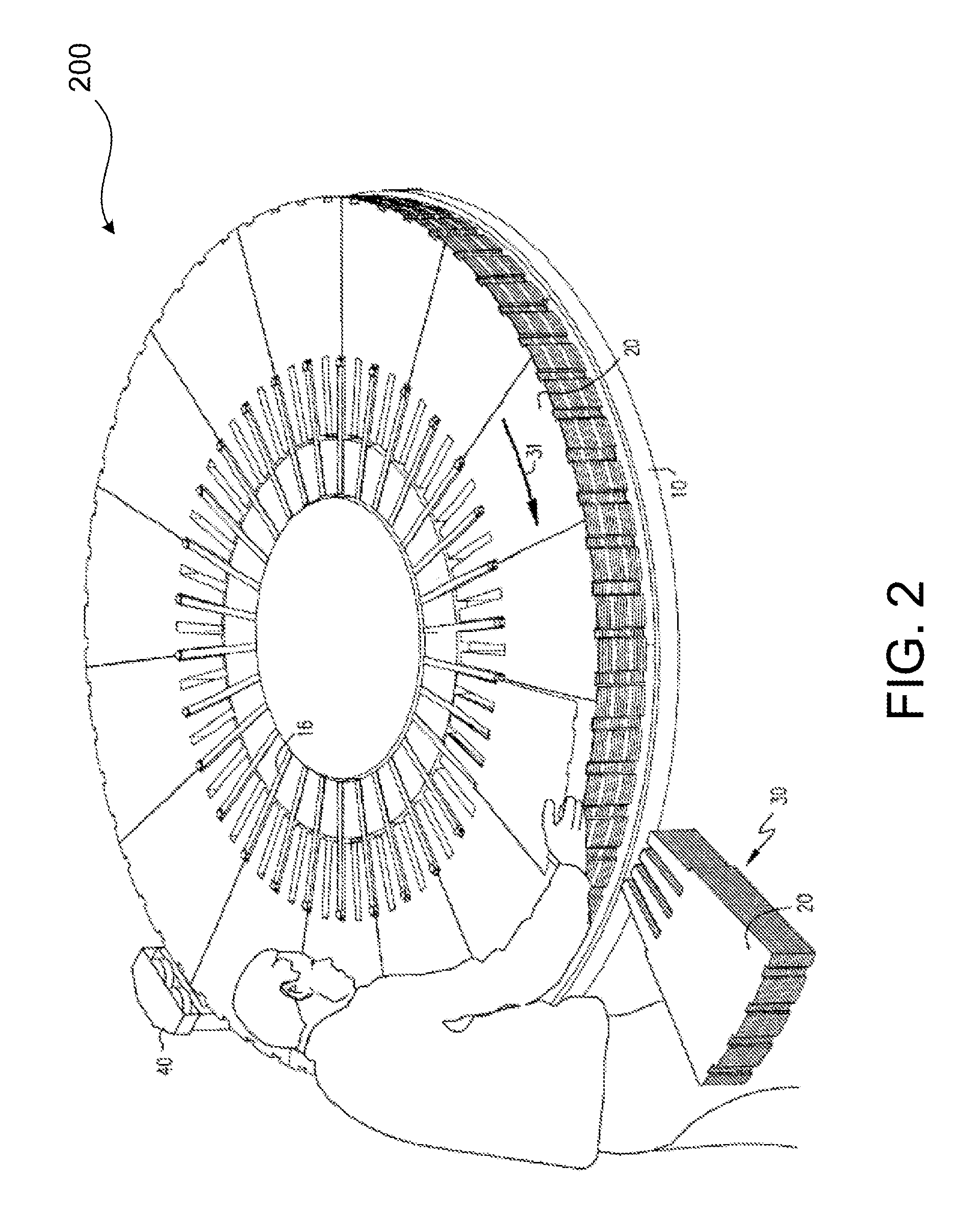
[0014]Referring now to the drawings, and particularly to FIGS. 1 and 2, there is illustrated a support, e.g., a table 10, mounted for rotation about an axis 12 by a suitable drive, for example, an electric, hydraulic or pneumatic motor, not shown. The table 10 is preferably annular in form and surrounds a mandrel 14 rotatable about axis 12 with table 10. Mandrel 14 is also adjustable in elevation relative to table 10. Like the table, the mandrel may be elevated by any suitable, drive, preferably an electric motor. As illustrated, the mandrel mounts a plurality of radially outwardly extending fingers 16 which are rotatable with the mandrel 14 and adjustable in height as the mandrel's height is adjusted. The tips of the fingers 16 terminate in guides 18 for gu...


PUM


Abstract

A method and apparatus is provided for compressing the lamination stack for a dynamoelectric machine. The apparatus includes a plurality of weight distribution plates and a plurality of pressing plates. The plurality of weight distribution plates are placed on one end of the lamination stack of the dynamoelectric machine. The plurality of pressing plates are placed on the plurality of weight distribution plates. A compressive force is applied to the lamination stack via the plurality of weight distribution plates and the plurality of pressing plates.

Description

BACKGROUND OF THE INVENTION[0001]The present invention described herein relates generally to an apparatus for dynamoelectric machines. More specifically, present invention relates to an apparatus for compressing the lamination stack in the core of a dynamoelectric machine.[0002]Stator core laminations, i.e., punchings, are generally arranged in a plurality of annular arrays thereof forming sets or packets of adjacent stator core laminations. The sets of annular arrays of laminations are axially spaced one from the other by space blocks and installed in a generator stator frame. The space blocks define ventilation passages for directing a cooling flow radially through the stator. Typically, the assembly of the laminations is performed manually by disposing the laminations on dovetail-shaped keybars which have male projections complementary to the female projections along the outer diameter of the individual laminations. During assembly, the lamination stack can develop undesirable wa...

Claims


Application Information

Patent Timeline
IPC IPC(8): H02K15/02B30B13/00
CPCH02K15/024
Inventor LAPE, BROCK MATTHEWBASARAN, NIHANPINK, GARY ROBERTWALKO, STEVEN CHARLESOLIVER, STUART ALAN
Owner GENERAL ELECTRIC CO
Features
  • Generate Ideas
  • Intellectual Property
  • Life Sciences
  • Materials
  • Tech Scout
  • Unparalleled Data Quality
  • Higher Quality Content
  • 60% Fewer Hallucinations
Learn More