Scalable shipping buffer having an integrated sorting function and corresponding method

a shipping buffer and integrated technology, applied in the direction of conveyors, loading/unloading, storage devices, etc., can solve the problems of large computing expenditure at the end of a superordinated controlling device (material flow computer), a lot of space is required, and the effect of reducing the floor spa

Inactive Publication Date: 2012-05-17
SSI SCHAEFER PEEM
View PDF13 Cites 82 Cited by
  • Summary
  • Abstract
  • Description
  • Claims
  • Application Information

AI Technical Summary

Benefits of technology

[0007]Therefore, it is an object of the present invention to provide a system and a method which allows reducing a floor space required in an order-picking system as far as possible without the need to abandon typical characteristics such as storing or resorting.

Problems solved by technology

In this case, the problem is that goods which are to be sent, for example, to the same subsidiary, need to be stored over a certain period of time in order to keep the number of delivery trips as low as possible.
It is a problem on principle to accumulate deliveries and prepare the same for a loading process.
Nevertheless, a lot of space is required for allowing building correspondingly long accumulation tracks in a shipping area of the order-picking system.
Another problem caused by the preparation of different goods is to be seen in the loading or unloading sequence of the goods.
This is disadvantageous in that a relatively space-consuming unit (conveyor circle in terms of a sorter) is used.
On the other hand, a significant computing expenditure at the end of a superordinated controlling device (material flow computer) can be caused, in particular if the orders are processed in parallel, in order to manage the goods of the different orders simultaneously, in particular when mixing and subsequently separating the same.

Method used


Image

  • Scalable shipping buffer having an integrated sorting function and corresponding method
  • Scalable shipping buffer having an integrated sorting function and corresponding method
  • Scalable shipping buffer having an integrated sorting function and corresponding method

Examples


first embodiment

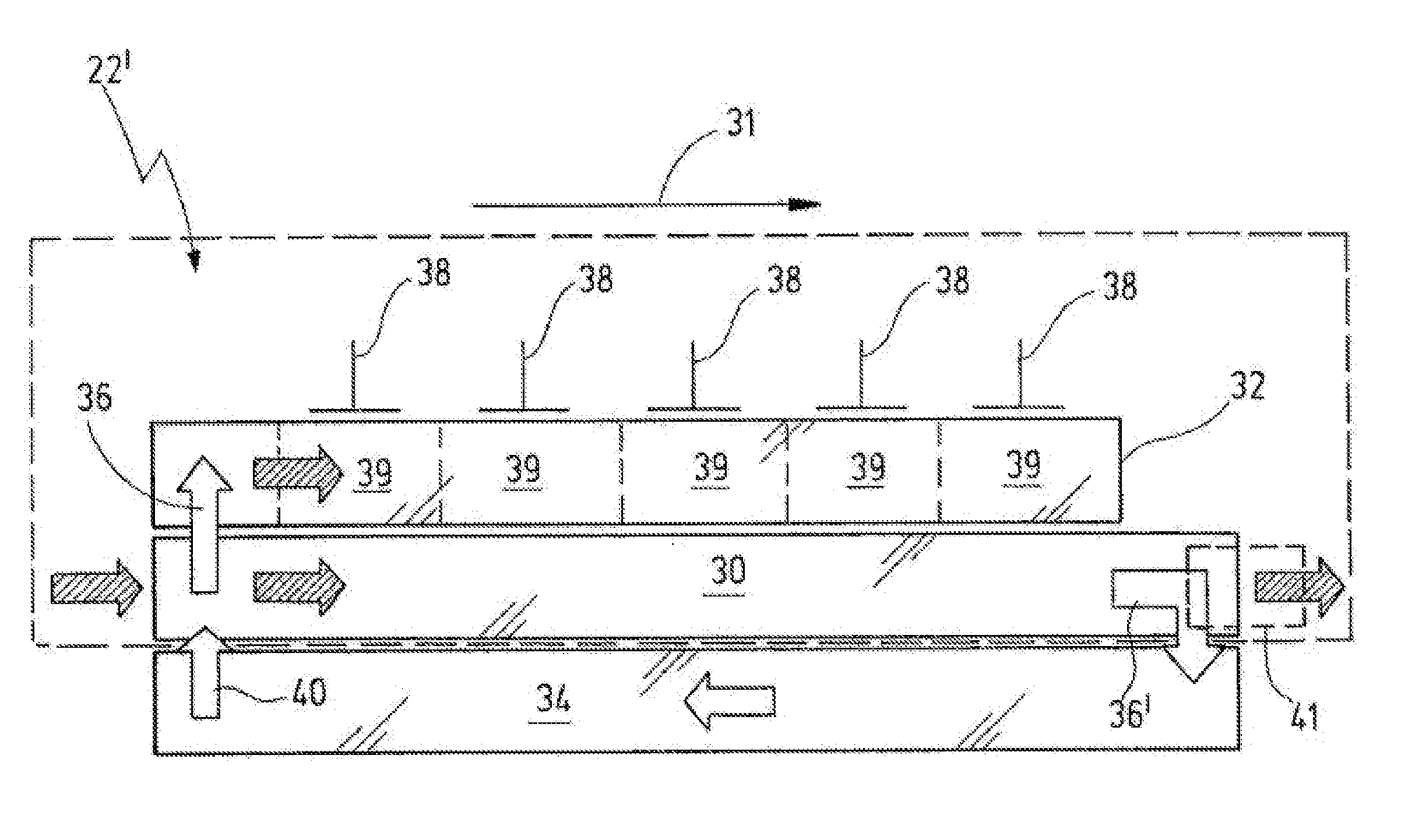
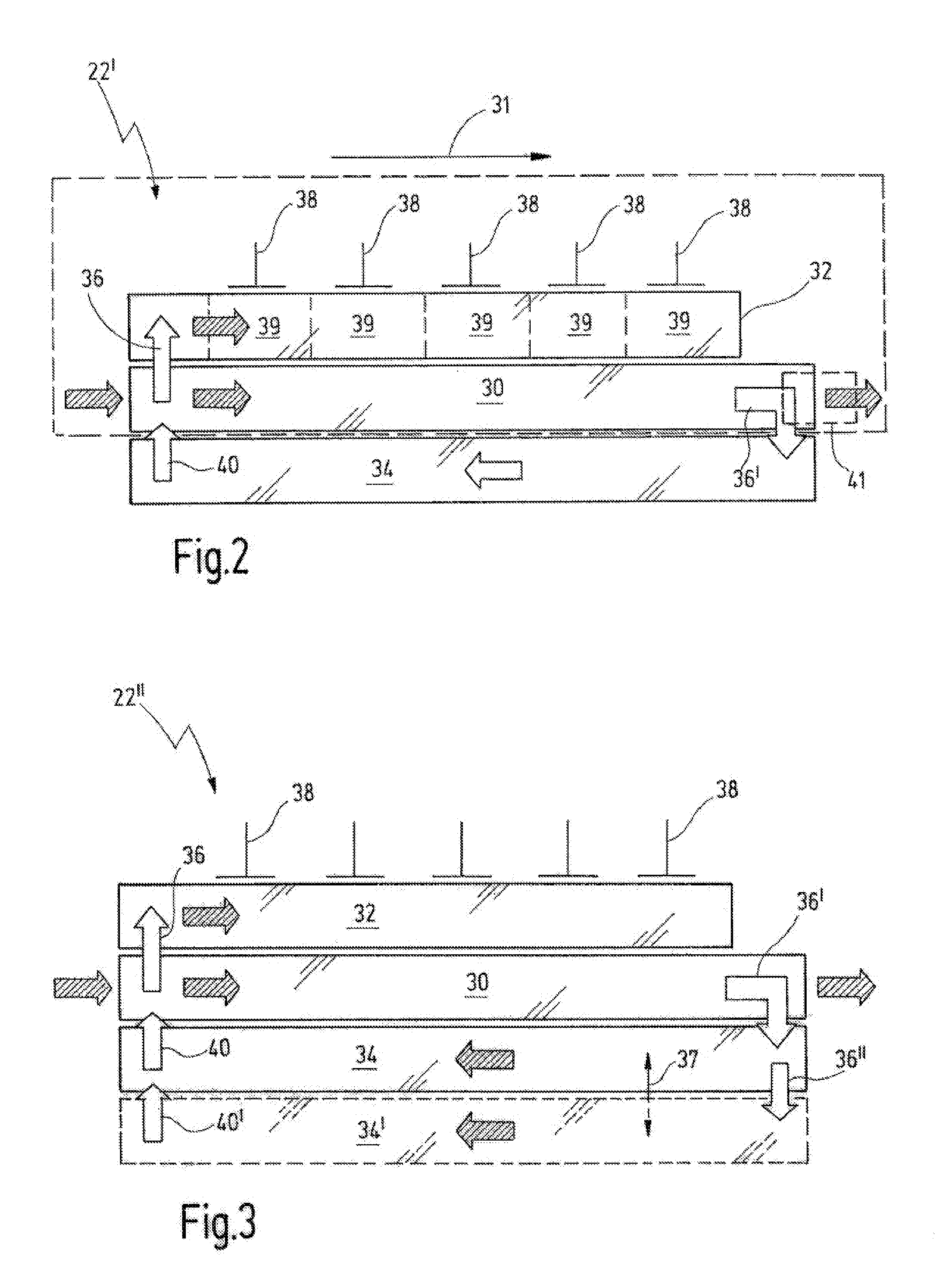
[0050]a shipping buffer 22′ is shown in FIG. 2, where goods, which are not depicted here, are transported on a withdrawal line 30 in a longitudinal direction 31, which is indicated by means of an arrow, from the left to the right in FIG. 1. The shipping buffer 22′ further comprises at least a first buffer line 32. The first buffer line 32 is arranged directly adjacent in longitudinal direction to the withdrawal line 30. It is clear that the first buffer line 32 could also be arranged at a greater distance relative to the withdrawal line 30 by providing corresponding conveyor bridges between the lines 30 and 32.

[0051]The withdrawal line 30 comprises, for example, at its upstream end a first feed device 36 for feeding goods from the withdrawal line 30 into the first buffer line 32. The feed device 36 is indicated by means of a dark vertical arrow in FIG. 2. It is clear that the feed device 36 could also be arranged at an outside location, e.g. in front of the lines.

[0052]Another feed ...

second embodiment

[0057]With reference to FIG. 3, a shipping buffer 22″ in accordance with the present invention is shown. The shipping buffer 22″ is distinguished from the shipping buffer 22′ in that an additional (third) buffer line 34′ adjoins to the second buffer line 34. Even further, an additional feed device 36″ is provided in the region of the downstream end of the second buffer line 34, allowing feeding goods from the second buffer line to the third buffer line 34′. In an analogous manner, a discharge device 40′ is provided at an upstream end of the third buffer line 34′, allowing discharging of goods from the third buffer line 34′ to the second buffer line 34. The storage capacity of the shipping buffer 22″ is increased by means of the third buffer line 34′ in comparison to the storage capacity of the shipping buffer 22′ of FIG. 2, i.e. by the buffer locations of the third buffer line 34′. An optionally provided line-change device is shown by a broken line between the second and third buffe...

embodiment 50

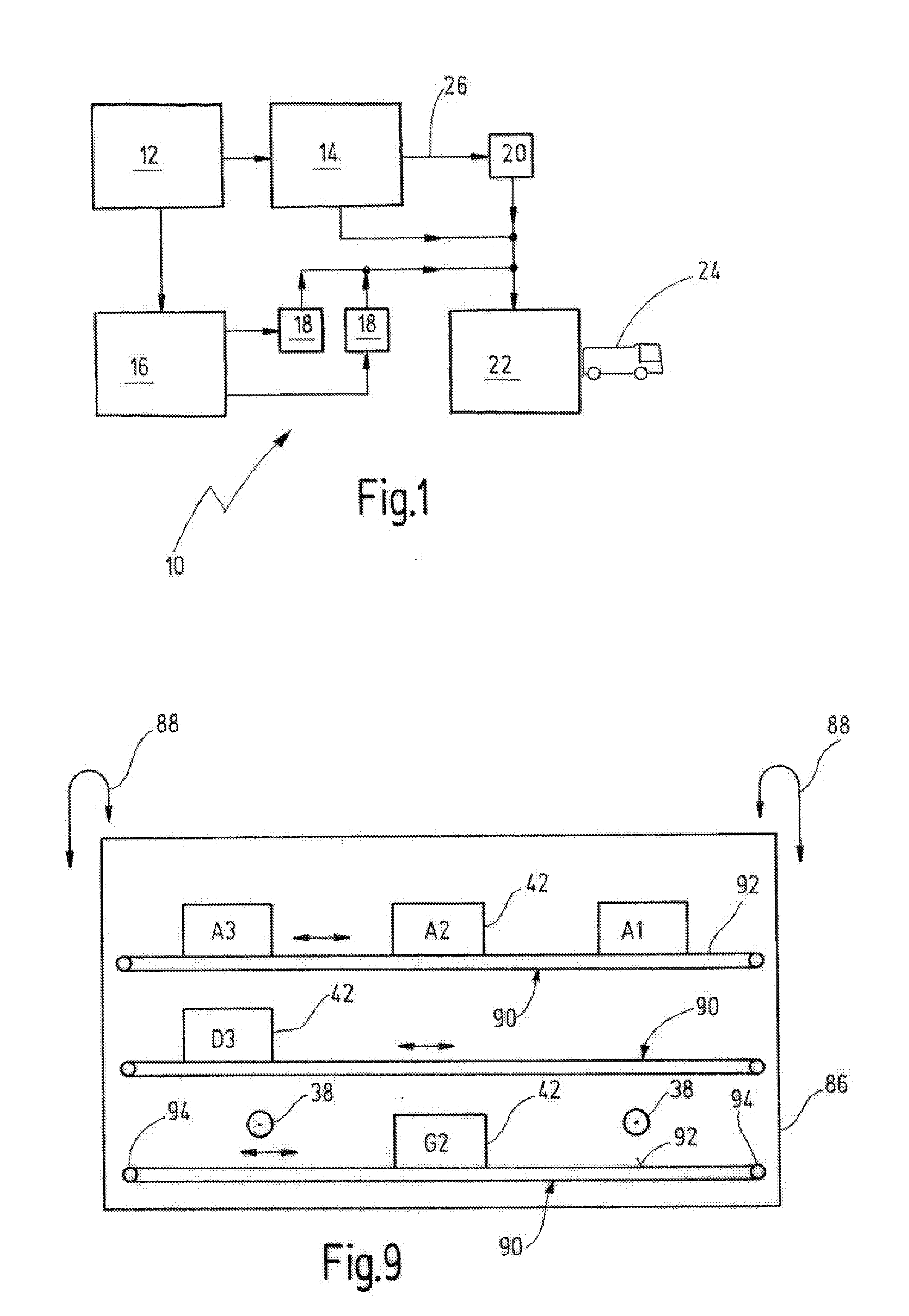
[0074]In FIG. 6b, the shipping buffer 50 of FIG. 6a is shown in a modified embodiment 50′. The transfer devices 38, 38′ are arranged both laterally to the first buffer line 32 and laterally to the second buffer line 34. In this case, the buffer lines 32 and 34 are operated only in a downstream direction. The feed device 36′ as well as the discharge device 40′ between the withdrawal line 30 and the second buffer line 34 have been saved. Therefore, the second buffer line 34 of FIG. 6b only conveys in the downstream direction, in contrast to the second buffer line 34 of FIG. 6a which can be operated in both directions as illustrated by a double arrow 54 in FIG. 6a.

[0075]The goods 42 can be pushed from the buffer lines 32 and 34 onto the withdrawal line 30 by means of the pushers 38, 38′. The goods 42 are then conveyed downstream towards the handover point 41, where they are distributed to the shipping locations VS1, . . . , VSn.

[0076]In FIG. 6c the material flow at the workstation 22′...


PUM


Abstract

A scalable shipping buffer (22; 50; 88) with an integrated sorting function for preparing a consignment comprising a number of different products (42), wherein the products (42) can be loaded into a transporting vehicle (24) in an ordered sequence and wherein the products (42) are delivered to the shipping buffer (22; 50; 88) in a disordered sequence, comprising: a drawing-off path (30), in particular a central drawing-off path, for conveying the products (42) in a downstream direction to a transfer point (41), at which the products (42) are transferred in the direction of the transporting vehicle (24) according to the ordered sequence, wherein the drawing-off path (30) extends essentially in a longitudinal direction (31); a first buffer path (32; 34), which extends essentially parallel and adjacent to the drawing-off path (30) and has a first number of buffer locations (39); a multiplicity of transfer devices (38), wherein the transfer devices are arranged in such a way that each buffer location (39) of the first buffer path is assigned at least one transfer device (38) for a transfer of one or more products (42) from the first buffer path (32) to the drawing-off path (30); and a feeding-in device (36; 52), which is arranged in such a way that the products (42) which are supplied to the drawing-off path (30) in the unordered sequence can be fed into the first buffer path (32).

Description

RELATED APPLICATIONS[0001]This is a continuation application of the co-pending international patent application WO 2010 / 012364 A1 (PCT / EP2009 / 004998) filed on Jul. 9, 2009 which claims priority of the German patent application DE 10 2008 036 564 filed on Jul. 30, 2008, which is fully incorporated herewith by reference.TECHNICAL FIELD[0002]The present invention relates to a scalable shipping buffer having an integrated sorting function as particularly used in a central retail warehouse for preparing truck loads in order to supply retail subsidiaries with goods in accordance with an order. The present invention further relates to a method for preparing a corresponding shipment of goods.BACKGROUND[0003]In conventional order-picking systems, individual picking orders are frequently received and processed over the day. Some orders can be picked immediately after the receipt. Other orders may not yet have come in, but will be received in the course of the day. In this case, it may also ha...

Claims


Application Information

Patent Timeline
Patent Type & Authority Applications(United States)
IPC IPC(8): B65G69/00
CPCB65G47/5186B65G47/5145
Inventor BUCHMANN, RAINERSUESS, HEIKOWINKLER, MAX
Owner SSI SCHAEFER PEEM
Why Eureka
Try Eureka