This helps you quickly interpret patents by identifying the three key elements:
Problems solved by technology
Method used
Benefits of technology
Benefits of technology
[0011]Compared to the prior front-illuminated device, the arrangement permits a higher density of conducting tracks and thus faster parallel transfer than hitherto, since the CCD is back-illuminated and the tracks do not obscure the charge collection sites, while allowing the drive connections to be made only at the sides of the array. Compared to the prior back-illuminated device, there is less than one conducting strip per row, and the arrangement is applicable to smaller pixels in the column direction.
Problems solved by technology
The reduced amplitude decreases the size of charge packets that can be moved and may allow them to spill, causing the image to appear smeared down the centre.
Some applications require a very fast parallel transfer so this is undesirable.
There is a penalty that the strips reduce the light reaching the pixels in front-illuminated devices, but this does not apply if the device is back-thinned and illuminated from the backside.
Unfortunately the nature of siliconwaferprocessing means that it is difficult to define fine metal features.
Therefore so far the technique has been limited to devices with large pixels with relatively wide electrodes in the column direction limiting its application
The strips are widely spaced to minimise the light-sensitive area they block, which restricts the amount by which the time constant is reduced, and are also driven at the sides and top of the light-sensitive area, which makes it difficult to adapt the design for frame transfer operation.
Method used
Image
Click on the blue label to locate the original text in one second.
Reading with bidirectional positioning of images and text.
Examples
first embodiment
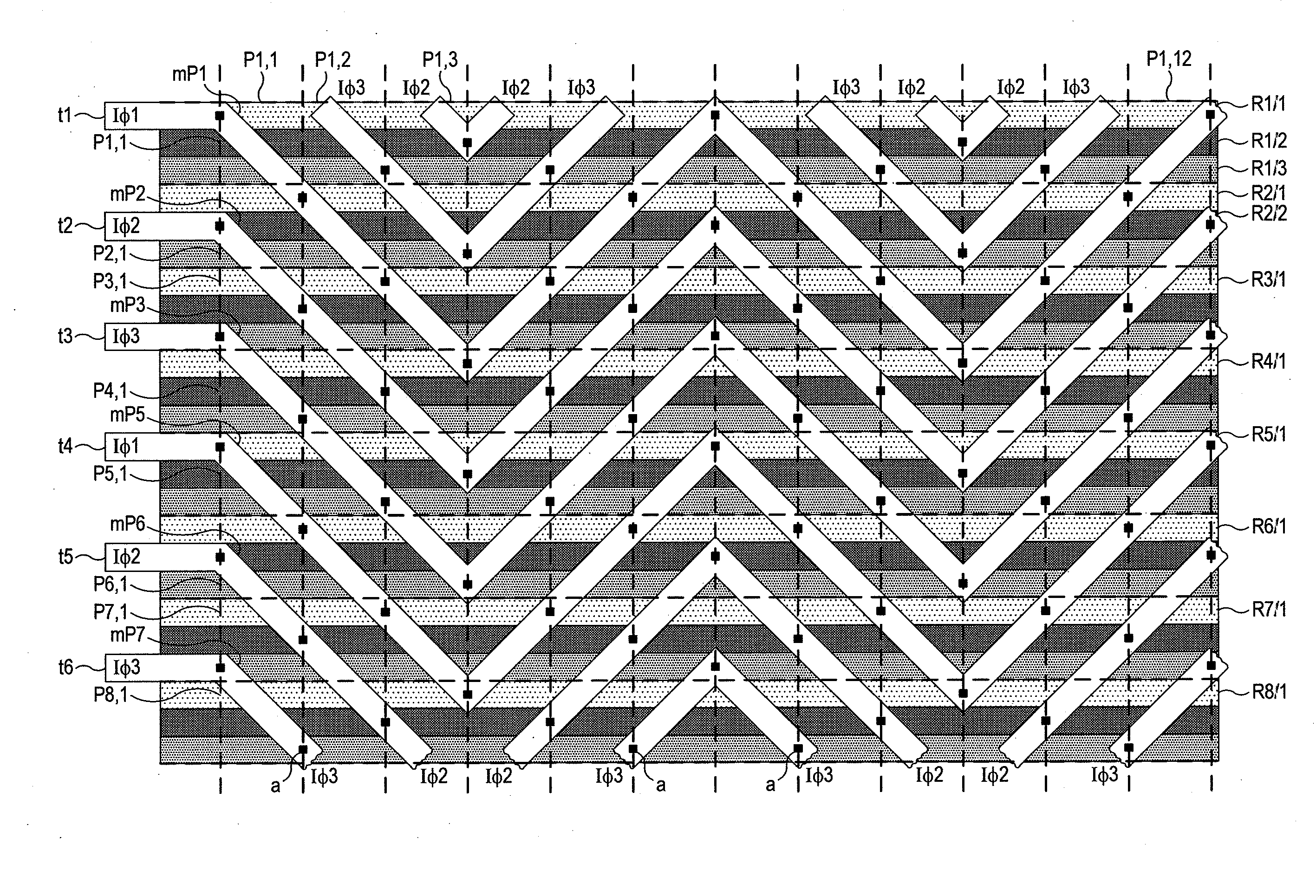
[0024]Referring to FIGS. 2 to 4, a fragmentary region of a back-illuminated full frame CCD according to the invention is shown. FIG. 3 shows a fragmentary region of the array, twelve pixels in the row direction, and eight in the column direction (P1,1, P1,2, P1,3 . . . P1,12 in the row direction and P1,1, P2,1, P3,1, . . . P8,1 in the column direction). FIG. 4 shows only two of the columns of pixels. In section, the CCD appears the same as the known CCD shown in FIG. 2.
[0025]In reality, the CCD would have hundreds of pixels in each row and hundreds in each column, a typical array extending 1024 by 1024. The CCD is seen in FIG. 3 in top plan, and the illumination strikes the CCD from beneath the plane of the drawing.
[0026]Referring to FIG. 4, the clocking voltages are applied by lines IΦ1 to IΦ3 to respective terminals t1 to t6. The rows of charge are transferred in parallel fashion to an output register 3, which outputs the charge in serial fashion in the direction of the arrow A.
[0...
second embodiment
[0038]Referring to FIGS. 2, 5 and 6, a frame transfer CCD is shown according to the invention. FIG. 5 shows rows of pixels on each side of the transition between image region and store region, namely, Pi1,1, Pi2,1, Pi3,1, Pi4,1, Pi5,1 and Pi6,1 in the image region 2 and Ps1,1, Ps2,1 in the store region 4. FIG. 5 shows twelve columns (up to Pi1,12) while FIG. 6 shows just two. In section, the CCD is the same as the prior art CCD of FIG. 2. In commercial devices, there would be hundreds of rows in the image region, for example, 1024 rows by 1024 columns in the image area, and typically slightly more rows in the store region. Each bottom row of the store region 2 is transferred to an output register 3, which has a serial output in the direction of the arrow A.
[0039]In such CCDs, the image region and store region of the CCD are operated by different clocking waveforms, the image region 2 by three phase image clocks (IΦ1, IΦ2 and IΦ3) and the store region 4 is clocked by three phase stor...
PUM
Abstract
A back-illuminated CCD includes a two-dimensional array of charge collection sites arranged in rows and columns. Each row is associated with a plurality of electrodes at the front face extending in the direction of the row and corresponding to respective phase voltages. A plurality of conducting strips is provided with each strip having repeatedly reversing inclined portions. Each portion is in electrical contact with the electrodes of a corresponding phase voltage of two or more rows. Each portion is inclined relative to the rows in the opposite direction to that in which the preceding portion is inclined.
Description
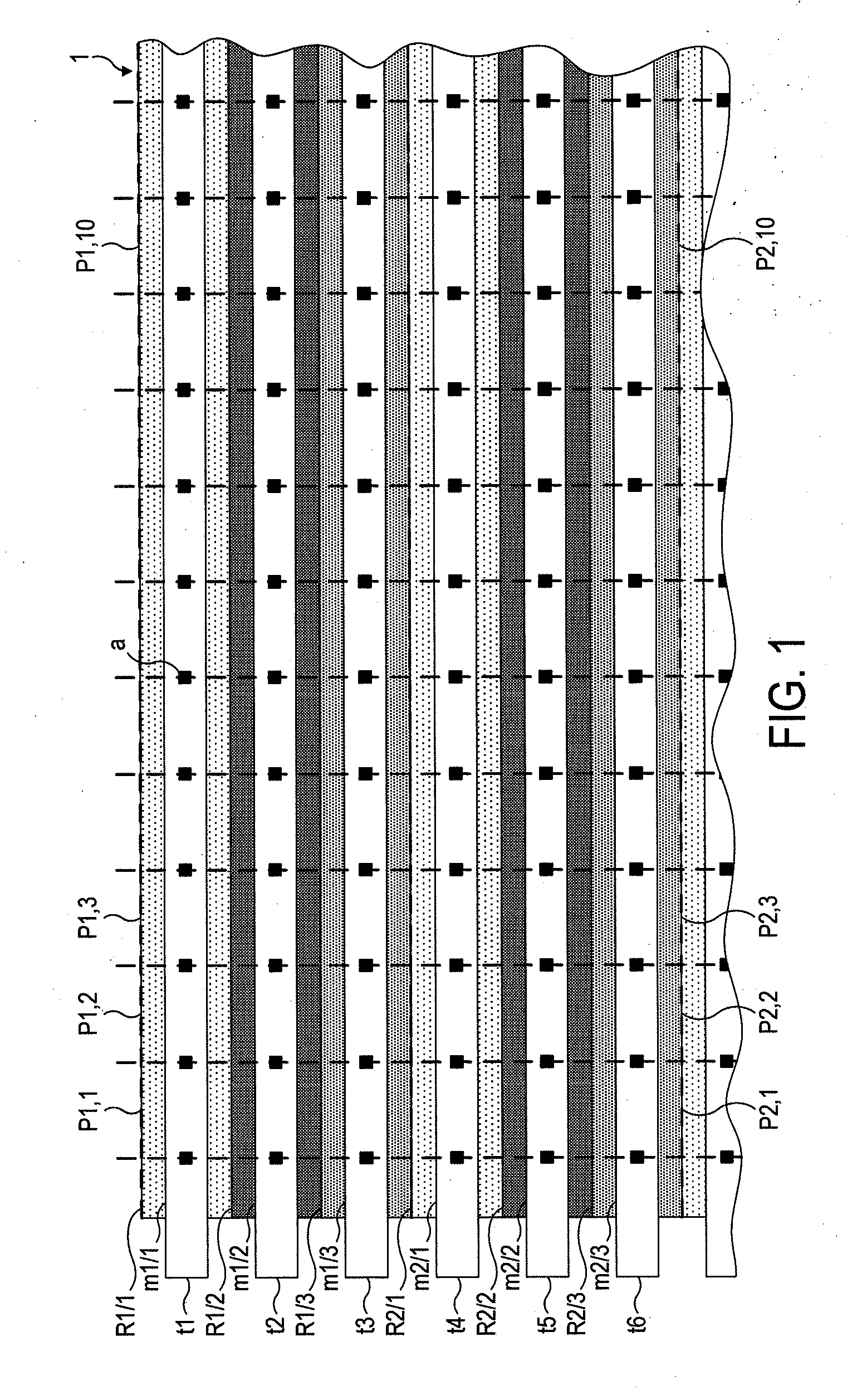
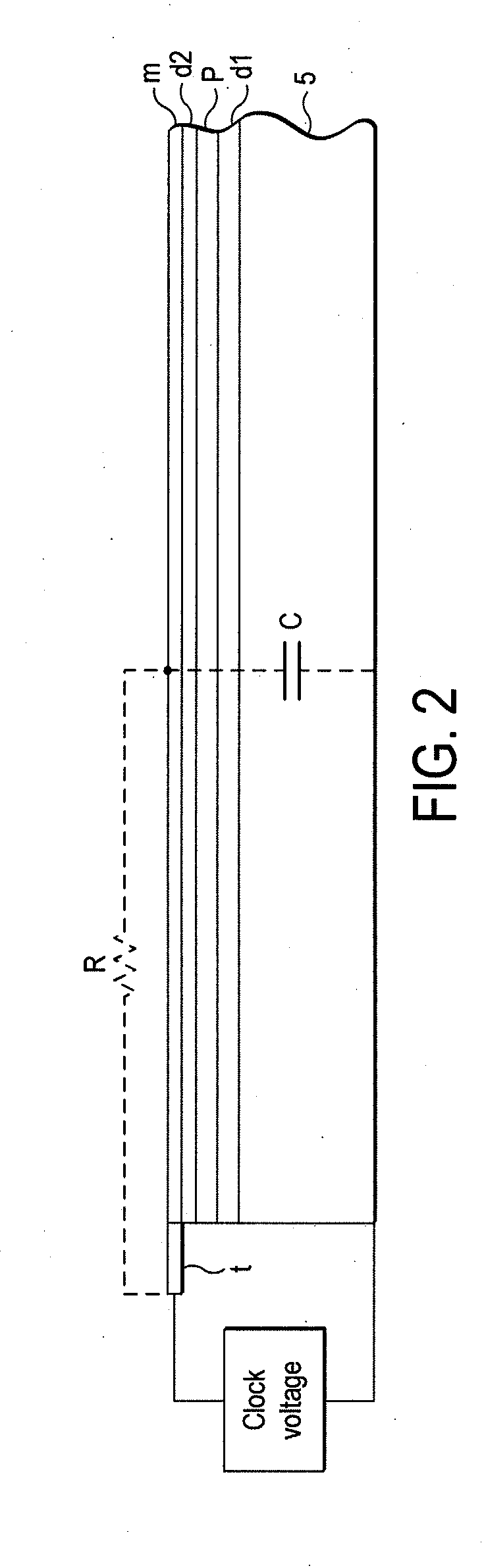
CROSS-REFERENCE TO RELATED APPLICATION[0001]This application claims the priority of the Great Britain Application No. 1019216.9, filed on Nov. 12, 2010, the subject matter of which is incorporated herein by reference.BACKGROUND OF THE INVENTION[0002]This invention relates to CCDs (charge coupled devices).[0003]FIG. 1 is a plan view of a part of a typical CCD, and FIG. 2 a sectional view. The CCD has an imaging area indicated generally by the reference numeral 1 consisting of an array of charge collection sites commonly known as pixels. The part of the array shown extends a little over ten pixels in the row direction and two in the column direction, and the pixels are denoted P1,1, P1,2, P1,3, . . . P1,10 in the first row and P2,1, P2,2, P2,3, . . . P2,10 in the second row. The scale in the column direction is enlarged compared to that in the row direction for the purposes of clarity. The full imaging area would typically extend to hundreds of pixels in each direction. In the vertica...
Claims
Application Information
Patent Timeline
Application Date:The date an application was filed.
Publication Date:The date a patent or application was officially published.
First Publication Date:The earliest publication date of a patent with the same application number.
Issue Date:Publication date of the patent grant document.
PCT Entry Date:The Entry date of PCT National Phase.
Estimated Expiry Date:The statutory expiry date of a patent right according to the Patent Law, and it is the longest term of protection that the patent right can achieve without the termination of the patent right due to other reasons(Term extension factor has been taken into account ).
Invalid Date:Actual expiry date is based on effective date or publication date of legal transaction data of invalid patent.

