Inkjet recording apparatus and image forming method
a recording apparatus and image technology, applied in the direction of printing, other printing apparatus, etc., can solve the problems of image defects, activation energy may occur, and cure defects
- Summary
- Abstract
- Description
- Claims
- Application Information
AI Technical Summary
Benefits of technology
Problems solved by technology
Method used
Image
Examples
first embodiment
[General Composition of Inkjet Recording Apparatus]
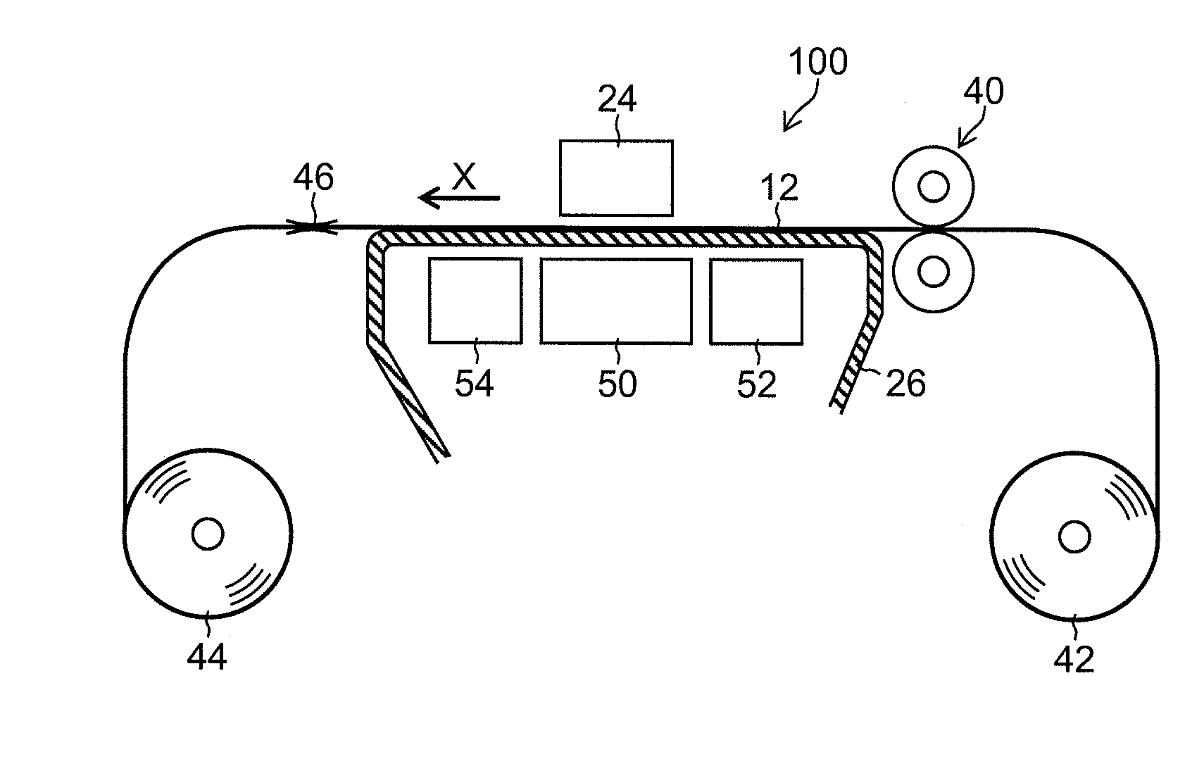
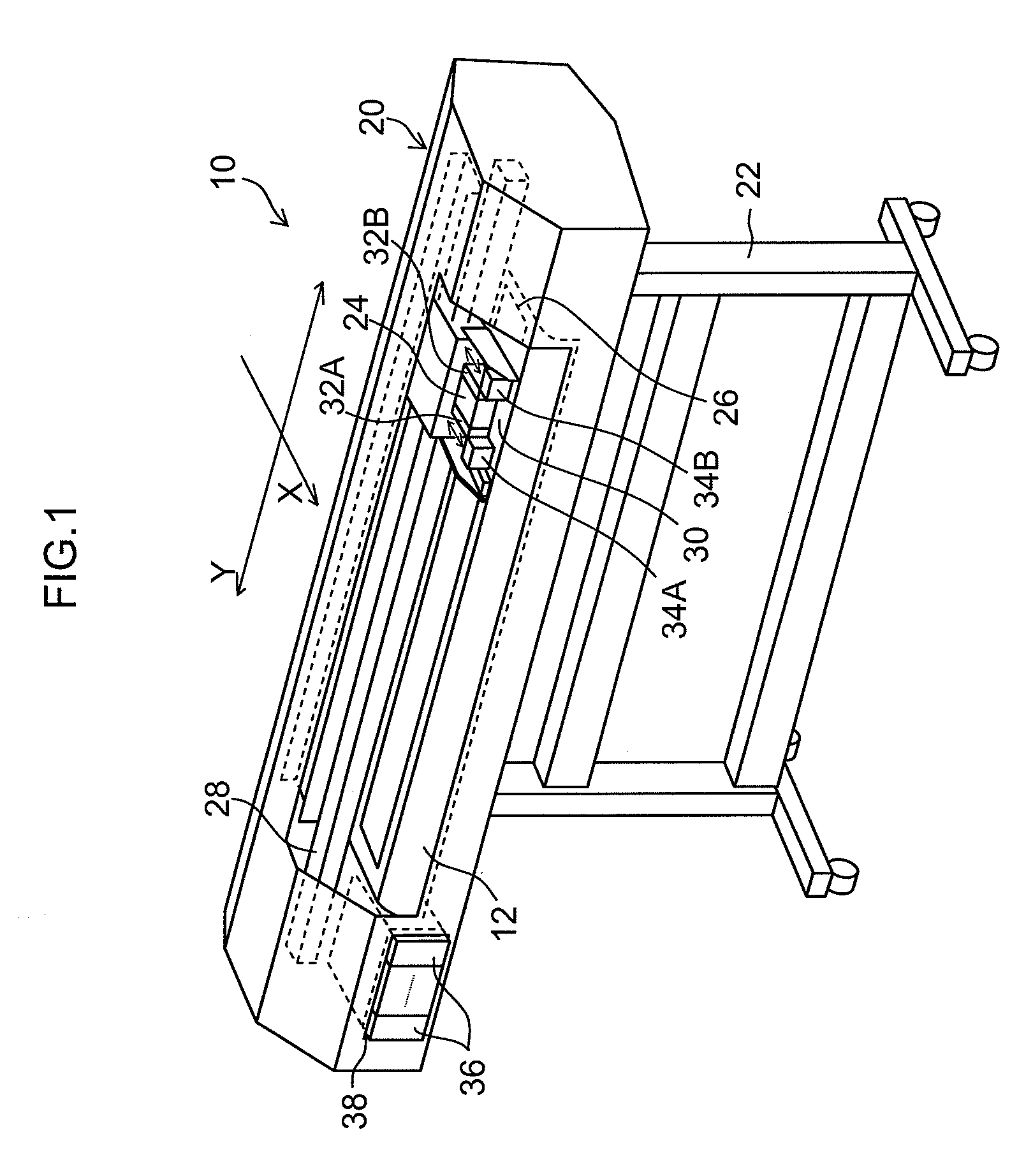
[0046]FIG. 1 is an external perspective drawing of an inkjet recording apparatus relating to a first embodiment of the present invention. This inkjet recording apparatus 10 is a wide-format printer which forms a color image on a recording medium 12 by using ultraviolet-curable ink (UV-curable ink). A wide-format printer is an apparatus which is suitable for recording a wide image formation range, such as for large posters or commercial wall advertisements, or the like. Here, a printer corresponding to a medium having a size of A3 with a predetermined margin or greater is called “wide-format”.
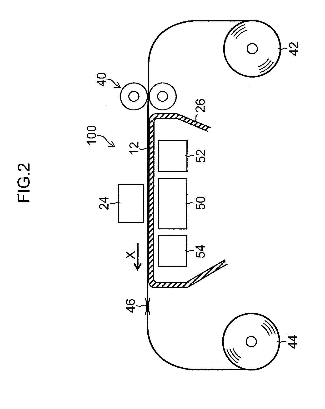
[0047]The inkjet recording apparatus 10 includes an apparatus main body 20 and a stand 22 which supports the apparatus main body 20. The apparatus main body 20 includes a drop-on-demand type of inkjet head 24 which ejects ink toward a recording medium (medium) 12, a platen 26 which supports the recording medium 12, and a guide mechanism 28 and a...
first specific example
[0083]FIG. 5 is an illustrative diagram showing a schematic view of the image layer structure formed by the image forming process relating to a first specific example. The image shown in FIG. 5 has a layered structure in which a white base layer 80 is formed on the recording medium 12, and a color image layer 82 is formed (layered) onto the white base layer 80, and hence the number of image forming layers is two.
[0084]FIG. 6 is an illustrative diagram showing a schematic view of the composition of an inkjet head 24 for forming an image having the layered structure shown in FIG. 5 and the arrangement of the main curing light sources 34A, 34B. The recording medium conveyance to direction (X direction) is the up to down direction indicated by the downward arrow in FIG. 6, and the reciprocating direction (Y direction) of the carriage 30 is a horizontal direction.
[0085]As shown in FIG. 6, the nozzle rows 61 are divided into two regions, an upstream region 61-1 and a downstream region 61-...
second specific example
[0097]FIG. 7 is an illustrative diagram showing a schematic view of the layer structure of the image formed by the image forming process relating to a second specific example, and FIG. 8 is an illustrative diagram showing a schematic view of the composition of an inkjet head 24 for forming an image having the layer structure shown in FIG. 7 and the arrangement of the main curing light sources 34A, 34B. In the following description, parts which are the same as or similar to the part described above are labeled with the same reference numerals and further explanation thereof is omitted here.
[0098]The image shown in FIG. 7 has two image forming layers, namely, a color image layer 82 which is formed on a transparent recording medium 12, and a white base layer 80 which is formed on the color image layer 82. When an image having this structure is viewed from the rear surface of the recording medium 12 (the surface opposite to the side where the image is formed), then the color image layer...
PUM
 Abstract
Description
Claims
Application Information
 - R&D
- Intellectual Property
- Life Sciences
- Materials
- Tech Scout
- Unparalleled Data Quality
- Higher Quality Content
- 60% Fewer Hallucinations
Browse by: Latest US Patents, China's latest patents, Technical Efficacy Thesaurus, Application Domain, Technology Topic, Popular Technical Reports.
© 2025 PatSnap. All rights reserved.Legal|Privacy policy|Modern Slavery Act Transparency Statement|Sitemap|About US| Contact US: help@patsnap.com


