
Ground fault detecting and controlling method for parallel-structured high voltage system

a high voltage system and ground fault technology, applied in the direction of testing circuits, instruments, electric devices, etc., can solve the problems of erroneous recognition of inability to accurately determine the ground fault situation of the system, and inability to measure the dielectric breakdown of the respective items of the system

Inactive Publication Date: 2012-05-17
HYUNDAI MOTOR CO LTD
View PDF1 Cites 10 Cited by
  • Summary
  • Abstract
  • Description
  • Claims
  • Application Information

AI Technical Summary

Benefits of technology

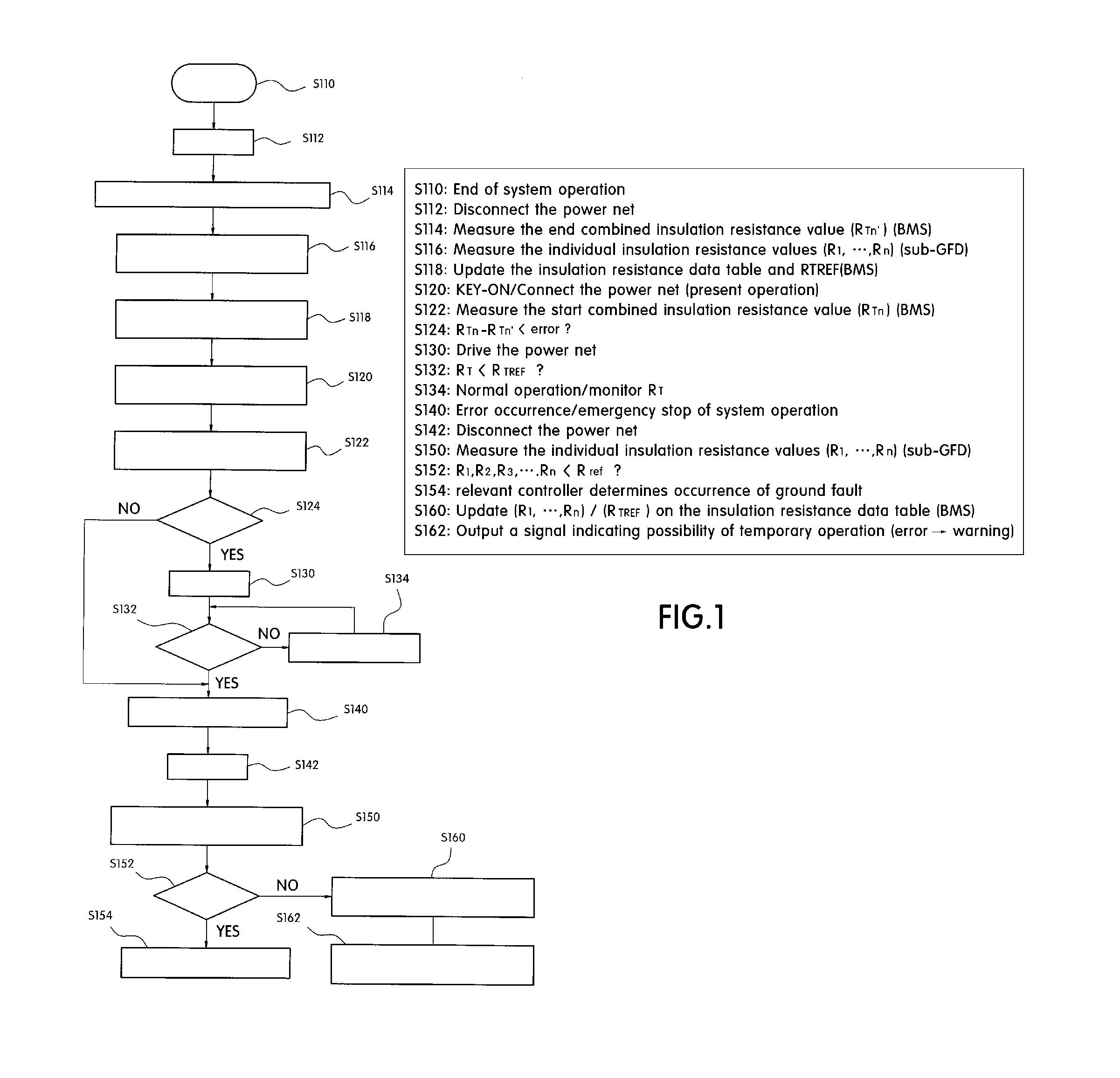
[0012]The present invention also relates to a ground fault detecting and controlling method for a parallel-structured high voltage system, in which system determines whether or not a ground fault occurs in an individual item based on an individual insulation resistance value measured through each auxiliary ground fault detector when the system emergency service is suspended. When this occurs, a driver is informed that a temporary operation of the system can be performed where any ground fault does not occur in all the individual items.
[0013]In order to accomplish the above object, the present invention provides a method for detecting and controlling a ground fault in a parallel-structured high voltage system, the method including: (a) measuring and updating an end combined insulation resistance value (RTn′) of a high voltage power net and individual insulation resistance values (R1, . . . , Rn) of respective items of the system, and calculating and updating a combined insulation resistance ground fault reference value (RTREF) based on the individual insulation resistance values (R1, . . . , Rn) in a previous system operation end step; (b) measuring a start combined insulation resistance value (RTn) of the high voltage power net, and comparing an error between the measured start combined insulation resistance value (RTn) and the end combined insulation resistance value (RTn′) in a present system operation start step; (c) measuring and updating the individual insulation resistance values (R1, . . . , Rn) of the respective items in real-time, and calculating and updating a combined insulation resistance value (RT) based on the individual insulation resistance values (R1, . . . , Rn); and (d) comparing the combined insulation resistance value (RT) measured at step (c) with the combined insulation resistance ground fault reference value (RTREF) measured at step (a) in real-time, whereby if it is determined that an error between the start combined insulation resistance value (RTn) and the end combined insulation resistance value (RTn′) is equal to or gre

Problems solved by technology

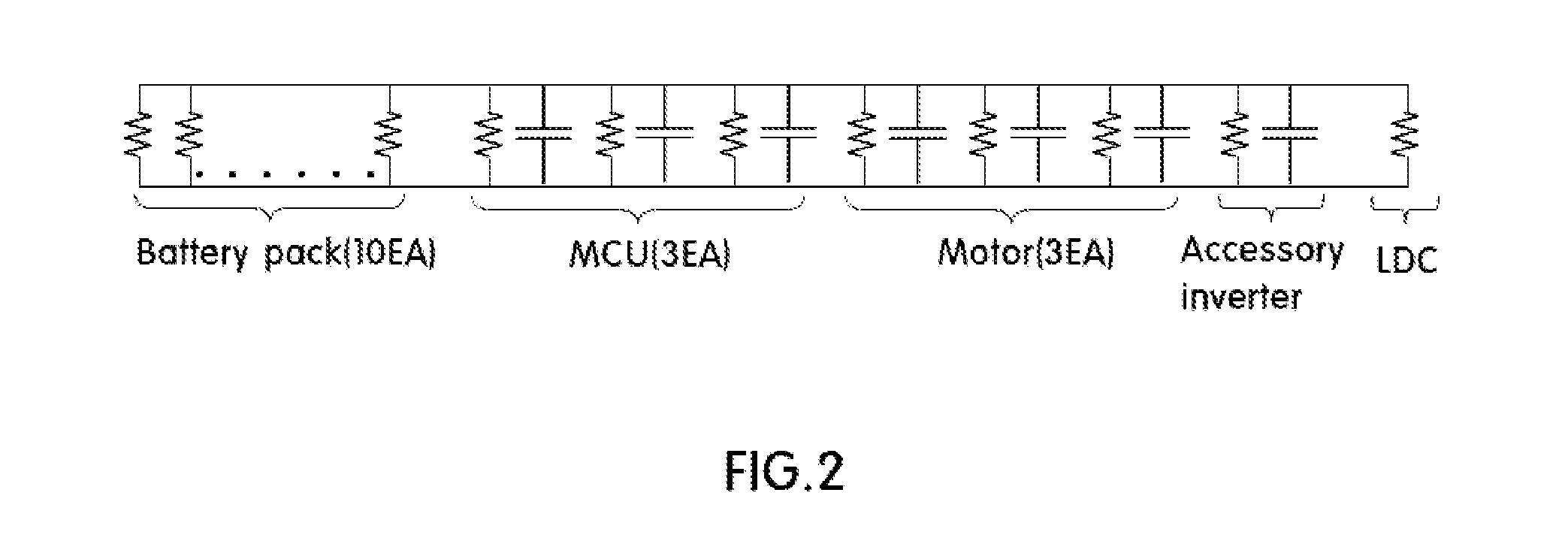
Accordingly, such a conventional prior art presents a problem because insulation resistance values of respective items of the parallel-structured system are not measured, but the total combined insulation resistance value of the system is measured.
Thus, the possibility of a dielectric breakdown of respective items of the system is not actually measured.
Therefore, when the detection of a ground fault is performed through the combined insulation resistance value of the parallel-structured system, even though an insulation resistance value of an individual item drops to less than an individual ground fault reference value (Rρ∈φ), a ground fault situation cannot be accurately determined.
Accordingly, a ground fault situation of the system is erroneously recognized.
Thus, the precise control of the system is impossible utilizing the conventional technique.

Method used


Image

  • Ground fault detecting and controlling method for parallel-structured high voltage system
  • Ground fault detecting and controlling method for parallel-structured high voltage system
  • Ground fault detecting and controlling method for parallel-structured high voltage system

Examples


Embodiment Construction

[0021]Reference will now be made in detail to the preferred embodiment of the present invention, examples of which are illustrated in the drawings attached hereinafter, wherein like reference numerals refer to like elements throughout. The embodiments are described below so as to explain the present invention by referring to the figures.

[0022]Now, an exemplary embodiment of according to the present invention will be described hereinafter in detail with reference to the accompanying drawings such that those skilled in that art to which the present invention pertains can easily carry out the embodiment.

[0023]The present invention provides a method for detecting and controlling a ground fault in a parallel-structured high voltage system in which a controller in a vehicle measures and updates a first combined insulation resistance value of a high voltage power net and one or more individual insulation resistance values of each respective item of the system; and determines whether the sy...


PUM


Abstract

The present invention relates to a ground fault detecting and controlling method for a parallel-structured high voltage system, and more particularly, such a ground fault detecting and controlling method for a parallel-structured high voltage system, in which it can be more precisely determined whether or not the system operation is emergently stopped based on individual insulation resistance values for respective items of the system, and it can be determined whether there is the possibility of temporary operation of the system in the emergency stop situation of the system operation. According to the present invention, a combined insulation resistance ground fault reference value is calculated based on individual insulation resistance values for respective items of the system, and the entire system is controlled by using the calculated combined insulation resistance ground fault reference value such that a high-accuracy ground fault detecting and controlling method can be provided.

Description

CROSS-REFERENCE TO RELATED APPLICATION[0001]This application claims the benefit under 35 U.S.C. §119(a) of Korean Patent Application No. 10-2010-0114172 filed in the Korean Intellectual Property Office on Nov. 17, 2010, the entire contents of which are incorporated herein by reference.BACKGROUND OF THE INVENTION[0002](a) Field of the Invention[0003]The present invention relates to a ground fault detecting and controlling method for a parallel-structured high voltage system, and more particularly, such a ground fault detecting and controlling method for a parallel-structured high voltage system, in which it can be more precisely determined whether or not the system operation is emergently stopped based on individual insulation resistance values for respective items of the system, and whether there is the possibility of temporary operation of the system in an emergency stop situation of the system operation.[0004](b) Background Art[0005]Recently, the spread of electric vehicles (EV), ...

Claims


Application Information

Patent Timeline
IPC IPC(8): G01R31/14H02H3/00
CPCB60L3/0069G01R31/025G01R31/007G01R31/52
Inventor YOON, SANG YON
Owner HYUNDAI MOTOR CO LTD
Learn More