Synchronous packet switches

packet switch technology, applied in hybrid switching systems, wavelength-division multiplex systems, electrical apparatus, etc., can solve the problems of increasing the footprint of the router, the overall power required by the router, and the power density of the entire router, so as to achieve the footprint and electrical power consumption requirements of a synchronous packet switch

Inactive Publication Date: 2012-05-17
TELEFON AB LM ERICSSON (PUBL)
View PDF6 Cites 9 Cited by
  • Summary
  • Abstract
  • Description
  • Claims
  • Application Information

AI Technical Summary

Benefits of technology

[0043]The method thus enables receipt of data cells in the electrical domain and switching of data cells in the optical domain, enabling the footprint and electrical power consumption requirements of a synchronous packet switch implementing the method to be reduced to less than that for equivalent known electronic routers.

Problems solved by technology

However, these all-electronic routers are approaching their fundamental limitations, mainly in terms of power density.
Multi-rack systems have been designed to reduce this problem but this solution further increases the overall power required by the router and the router footprint, and poses problems related to inter-rack wiring and communications.
All-optical packet switching networks, i.e. networks where optical packets are optically forwarded end-to-end, have been proposed but do not to satisfy the huge bandwidth and cost-effectiveness requirements of next generation backbone networks.
Hybrid optical / electrical routers have been proposed, such as the hybrid electronic / optical switch system described in U.S. Pat. No. 6,647,208, in which some optical data is routed optically and other optical data is optical to electronic (O / E) converted and routed electronically, to reduce the amount of data being routed electronically, however such hybrid switches require very complicated control systems.

Method used


Image

  • Synchronous packet switches
  • Synchronous packet switches
  • Synchronous packet switches

Examples


first embodiment

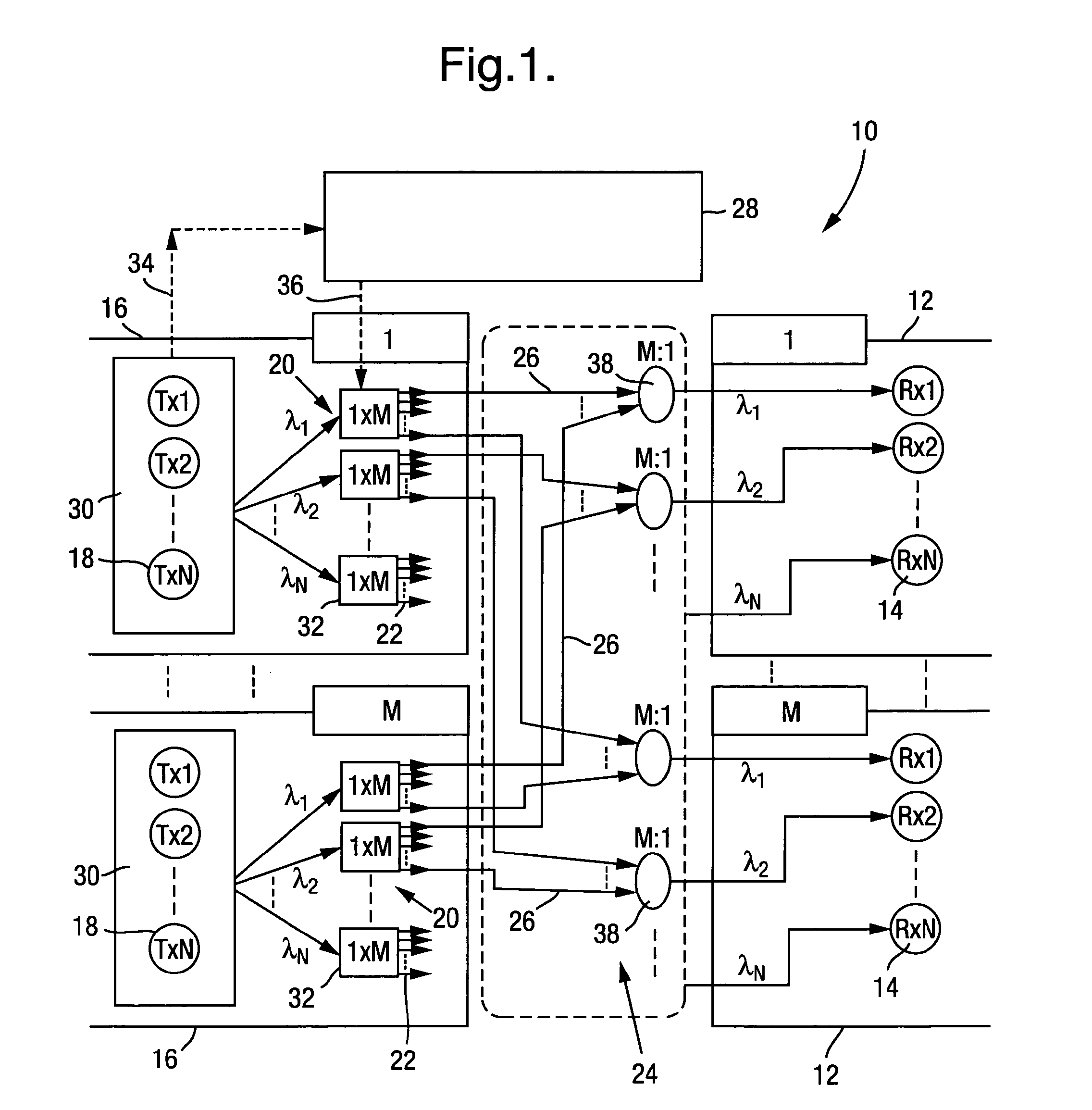
[0067]Referring to FIG. 1, the invention provides a synchronous packet switch 10 comprising M output modules 12 (only two are shown for clarity), M input modules 16 (only two are shown for clarity), optical connections 26, 38 and a switch control unit 28. The switch 10 is arranged to switch data in the optical domain and is arranged to receive electrical signals carrying data cells to be routed and to transmit further electrical signals carrying data cells having been switched. The synchronous packet switch 10 is operable to route fixed length packets of cells at each packet time.

[0068]Each output module 12 comprises N optical receivers 14, which in this example comprise fixed wavelength photo detectors. Each optical receiver 14 is configured to receive optical signals at a different 1 of N wavelengths (λ1-λN).

[0069]Each input module 16 terminates N input channels, each delivering electrical signals carrying data cells to be routed by the switch 10. Each input module 16 comprises N ...

third embodiment

[0086]the invention provides a synchronous packet switch 60, as shown in FIG. 3. The synchronous packet switch 60 of this embodiment is substantially the same as the synchronous packet switch 40 of the previous embodiment, with the following modifications. The same reference numbers are retained for corresponding features.

[0087]In this example the optical connections comprise solely of optical fibres 26, simplifying the optical backplane 24. The couplers 38 of the previous embodiments are replaced by N M×1 optical switches 64 in each output module 62. The M inputs of each optical switch 64 are coupled via the optical fibres 26 to the respective output ports 22 of the optical switches 32 in the input modules 44. Each optical switch 64 only receives optical signals at one of the N wavelengths (λ1 to λN) and the output of each optical switch 64 is connected to the respective one of the optical receivers 14 configured to receive that wavelength. The switch control unit 28 is further ope...

fourth embodiment

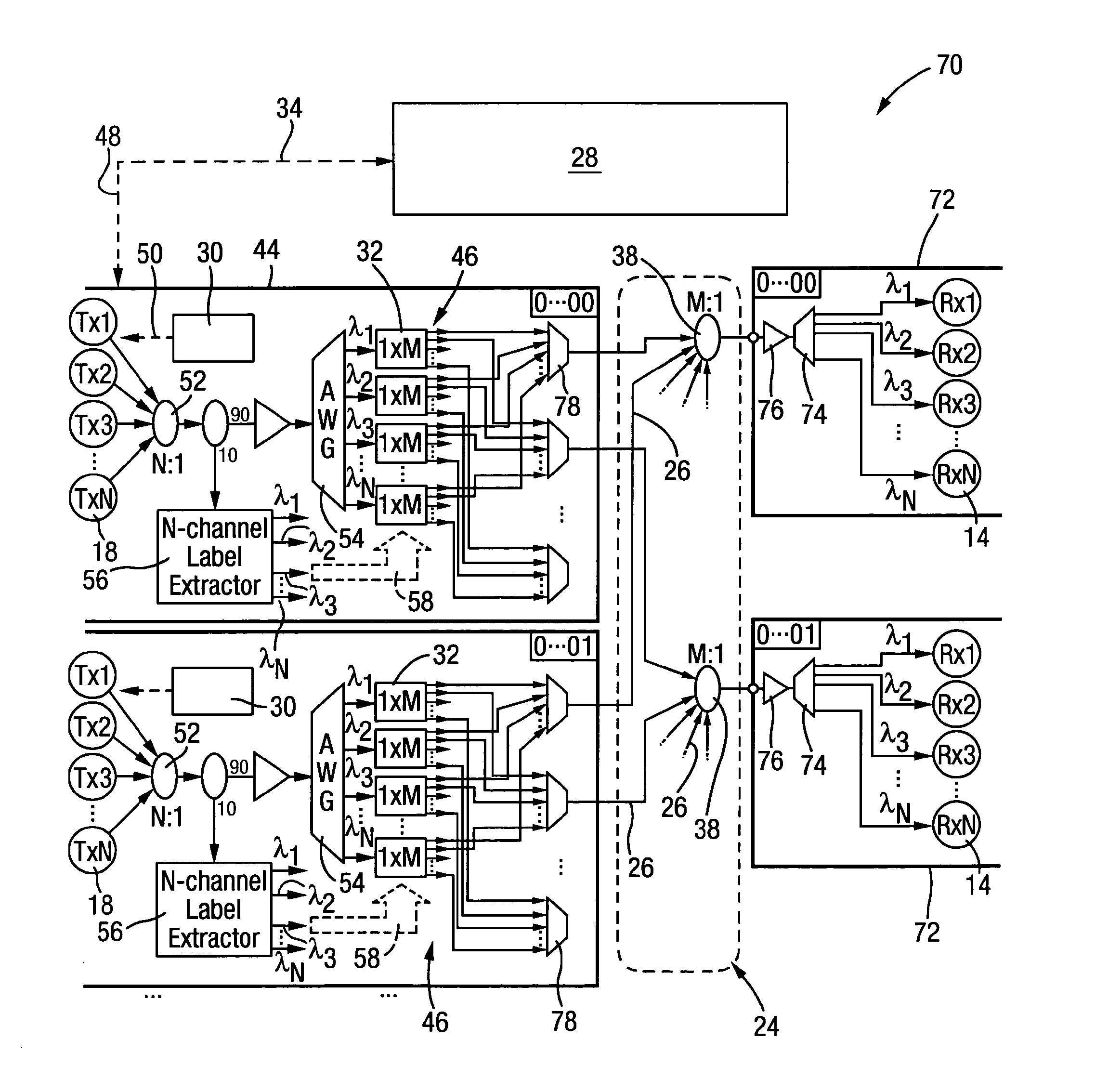
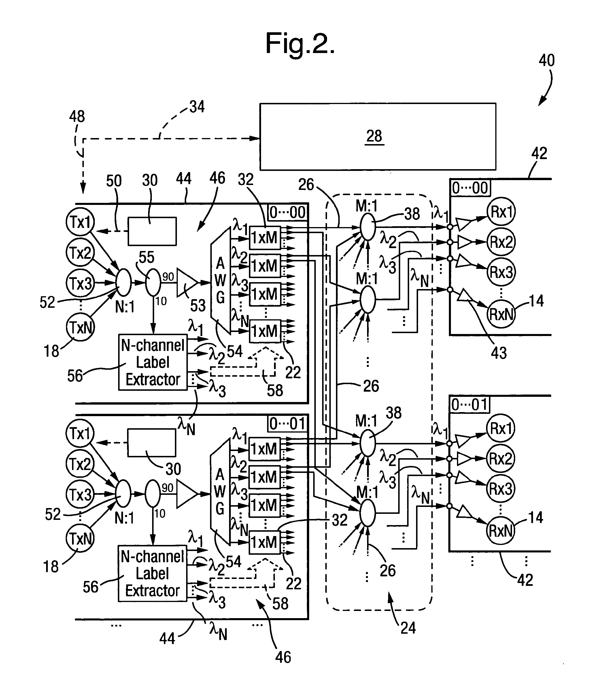
[0088]the invention provides a synchronous packet switch 70 as shown in FIG. 4. The synchronous packet switch 70 of this embodiment is substantially the same as the synchronous packet switch 40 shown in FIG. 2, with the following modifications. The same reference numerals are retained for corresponding features.

[0089]In this embodiment the routing apparatus 46 further comprises M output multiplexers, in the form of AWGs 78. Each AWG has N input ports, each for receiving an optical signal at a different one of the N wavelengths. Each input port of an AWG 78 is coupled to an output port of one of the optical switches at the respective wavelength. Each AWG 78 is arranged to multiplex received optical signals for routing to a selected output module 72.

[0090]In this example, the optical connections comprise optical fibres 26 and M M:1 optical couplers 38, provided in the optical back plane 24. The number of optical fibre 26 and M:1 couplers 38 is thus reduced compared to the switch 40 of...


PUM


Abstract

A synchronous packet switch comprises output modules, input modules, optical connections and a switch control unit. The output modules comprise optical receivers each configured to receive optical signals at a different wavelength. The input modules receive electric signals carrying data cells to be routed. Each input module comprises optical transmitters, each configurable to generate an optical signal at a different wavelength, and routing apparatus comprising output ports. Each output module has at least one output port allocated to it. The routing apparatus is configurable to route a received optical signal to a selected output port. The optical connections are arranged to couple output ports to respective output modules. The switch control unit controls routing of the optical signals from the transmitters to the output modules and generates a routing control signal for configuring the routing apparatus to route an optical signal from a transmitter to a selected output port.

Description

FIELD OF THE INVENTION[0001]The invention relates to a synchronous packet switch, to a collector card for a synchronous packet switch and to a method of routing data in a synchronous packet switch.BACKGROUND OF THE INVENTION[0002]The amount of data required to be handled by communications networks continues to rise. Next generation backbone networks will have to cope with data traffic arriving from more and faster interfaces, and will need to provide a data throughput in the range of tens or hundreds of Terabits per second (Tb / s). High-end routers in backbone networks are typically all-electronic, with all routing functions realized in the electronic domain. However, these all-electronic routers are approaching their fundamental limitations, mainly in terms of power density. Multi-rack systems have been designed to reduce this problem but this solution further increases the overall power required by the router and the router footprint, and poses problems related to inter-rack wiring...

Claims


Application Information

Patent Timeline
Patent Type & Authority Applications(United States)
IPC IPC(8): H04J14/02
CPCH04L12/6402H04Q11/0005H04Q11/0066H04Q2011/0009H04Q2011/0039H04Q2011/0018H04Q2011/0022H04Q2011/0032H04Q2011/0015
Inventor ANDRIOLLI, NICOLABOGONI, ANTONELLABIANCHI, ALBERTOCASTOLDI, PIEROPOTI, LUCARAPONI, PIER GIORGIO
Owner TELEFON AB LM ERICSSON (PUBL)
Why Eureka
Try Eureka