
Radio base station and handover control method

a control method and radio technology, applied in the direction of electrical equipment, wireless communication, etc., can solve the problems of wasting radio resources affecting the service initialization, and limited communication coverage of the next-generation radio communication system when a service is started

Inactive Publication Date: 2012-05-17
KYOCERA CORP
View PDF3 Cites 7 Cited by
  • Summary
  • Abstract
  • Description
  • Claims
  • Application Information

AI Technical Summary

Benefits of technology

[0008]Therefore, an object of the present invention is to provide a radio base station which can effectively utilize a radio communication system capable of performing high-speed communication, and a handover control method, when a plurality of radio communication systems exist.
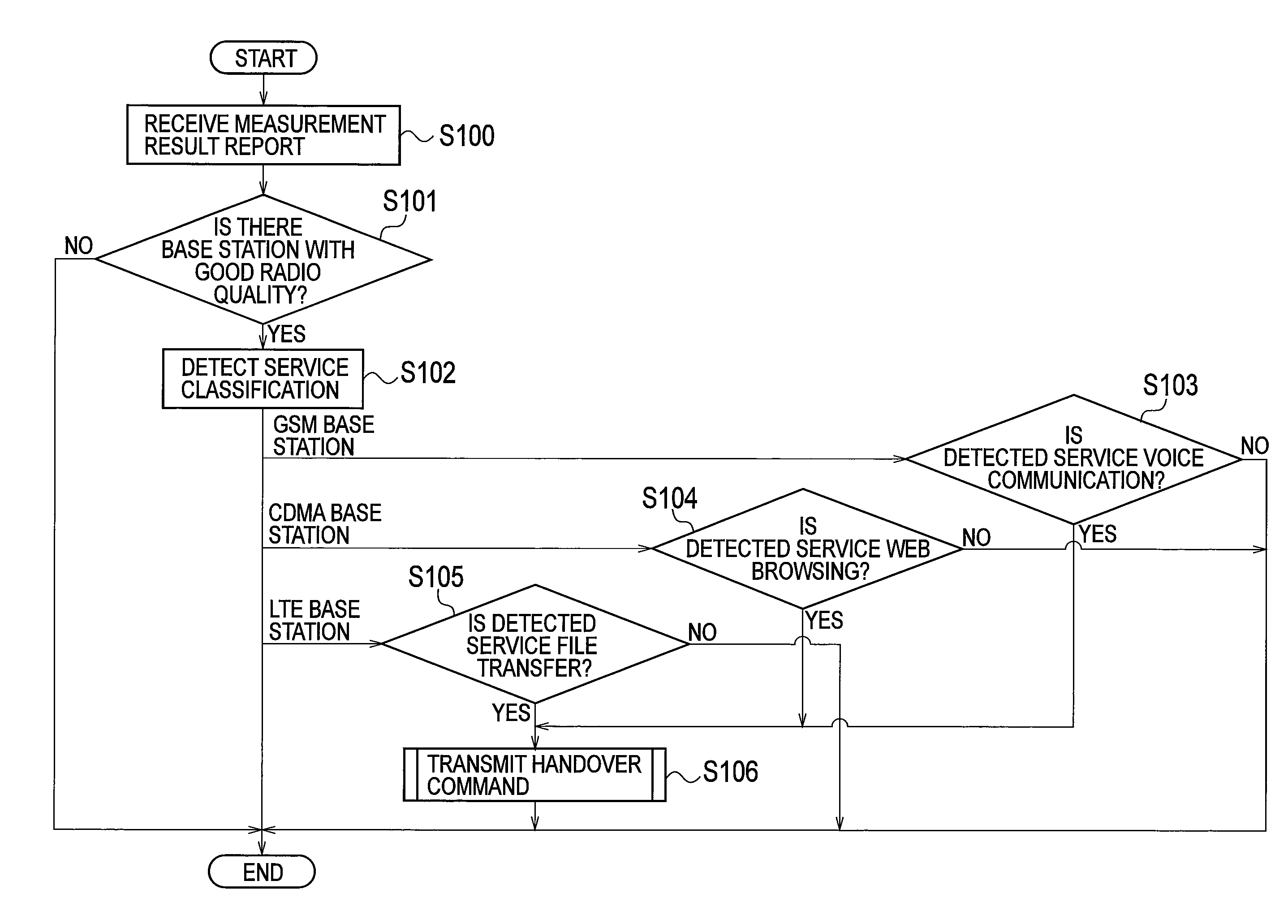
[0010]According to such a feature, when the communication rate required for each type of communication service used by the radio terminal is low, it is possible to make the radio terminal to perform a handover toward a radio communication system with a lower communication rate. Moreover, when the communication rate required for each type of the communication service used by the radio terminal is high, it is possible to make the radio terminal to perform a handover toward a radio communication system capable of a high-speed communication.
[0011]Therefore, it is possible to provide that the radio resource of a radio communication system (i.e., a next-generation radio communication system) capable of a high-speed communication is preferentially used for the radio terminal that is using a communication service requiring a high-speed communication rate. This enables effective use of a radio communication system capable of a high-speed communication.
[0015]Therefore, it is possible to provide that the radio resource of a radio communication system (e.g., a next-generation radio communication system) capable of a high-speed communication is preferentially used for the radio terminal that needs to perform a high-speed radio communication (i.e., a radio terminal that is using a communication service requiring a high-speed communication rate). This enables effective use of a radio communication system capable of a high-speed communication.
[0019]According to the characteristics of the present invention, it is possible to provide a radio base station which can effectively utilize a radio communication system capable of performing high-speed communication, and a handover control method, when a plurality of radio communication systems exist.

Problems solved by technology

Meanwhile, since a radio base station compatible with the next-generation radio communication system has been gradually installed, a communication coverage of the next-generation radio communication system is limited when a service initially starts.
However, when a radio terminal using a communication service (for example, a voice communication service) requiring a low communication rate is connected to the radio base station of the next-generation radio communication system, a high communication rate of the next-generation radio communication system may not be provided and a radio resource of the next-generation radio communication system may be wasted.
Therefore, there is a problem that it is not possible to effectively utilize a radio communication system capable of a high-speed communication, as with the next-generation radio communication system.

Method used


Image

  • Radio base station and handover control method
  • Radio base station and handover control method
  • Radio base station and handover control method

Examples


first embodiment

(1) First Embodiment

[0031]In the first embodiment, (1.1) Configuration Example of Communication System, (1.2) Configuration of LTE Base Station, (1.3) Operation of LTE Base Station, and (1.4) Operation and Effect will be described.

(1.1) Configuration Example of Communication System

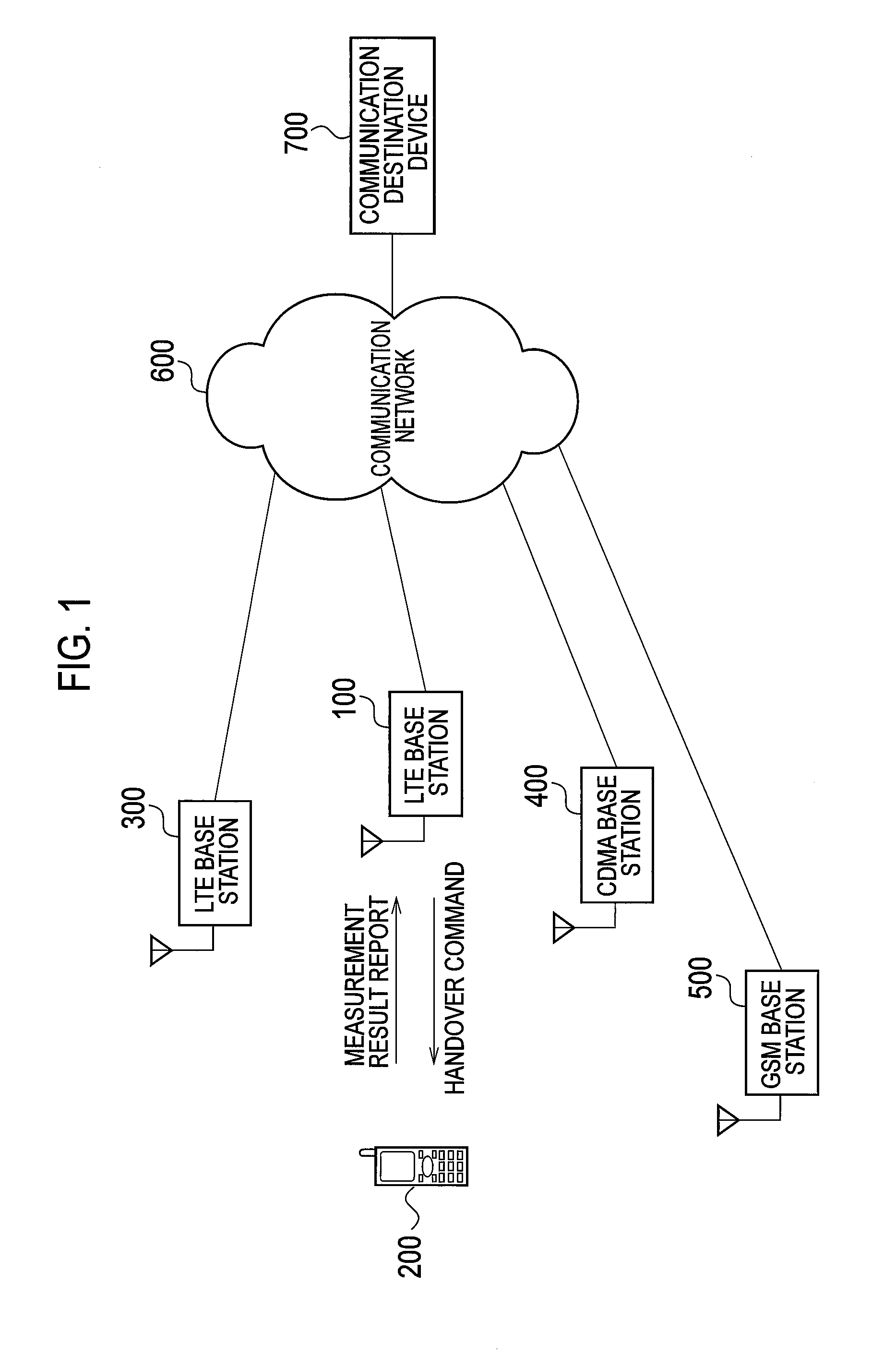
[0032]The communication system illustrated in FIG. 1 includes an LTE base station 100, a radio terminal 200, an LTE base station 300, a CDMA base station 400, a GSM base station 500, a communication network 600, and a communication destination device 700. The radio terminal 200 has established a radio connection to the LTE base station 100, and communicates with the communication destination device 700 such as a server or a communication terminal via the LTE base station 100 and the communication network 600. In the example of FIG. 1, only one radio terminal 200 is connected to the LTE base station 100. However, actually, a plurality of radio terminals 200 are connected to the LTE base station 100.

[0033]Th...

second embodiment

(2) Second Embodiment

[0072]In the first embodiment, a radio base station (a handover destination) is decided according to both the classification of a communication service being used by the radio terminal 200 and radio quality. In a second embodiment, instead of the classification of the communication service, a communication rate of radio communication with the radio terminal 200 is used.

[0073]In the second embodiment, (2.1) Configuration of LTE Base Station, (2.2) Operation of LTE Base Station, and (2.3) Operation and Effect will be described, and the description overlapping the first embodiment will be omitted.

(2.1) Configuration of LTE Base Station

[0074]FIG. 5 is a block diagram illustrating the configuration of the LTE base station 100 according to the second embodiment.

[0075]As illustrated in FIG. 5, the LTE base station 100 includes a communication rate measurement unit 121B, instead of the service detection unit 121A described in the first embodiment. The communication rate...

third embodiment

(3) Third Embodiment

[0090]In the third embodiment, the LTE base station 100 performs control such that an offset value is added to radio quality measured in the radio terminal 200 according to the classification of a communication service being used by the radio terminal 200.

[0091]In the third embodiment, (3.1) Configuration of LTE Base Station, (3.2) Operations of LTE Base Station and Radio Terminal, and (3.3) Operation and Effect will be described, and the description overlapping the first embodiment will be omitted.

(3.1) Configuration of LTE Base Station

[0092]FIG. 8 is a block diagram illustrating the configuration of the LTE base station 100 according to the third embodiment.

[0093]As illustrated in FIG. 8, the third embodiment is different from the first embodiment in that the LTE base station 100 further includes a measurement control unit 123 and a handover determination unit 124.

[0094]The measurement control unit 123 controls the measurement of radio quality in the radio term...


PUM


Abstract

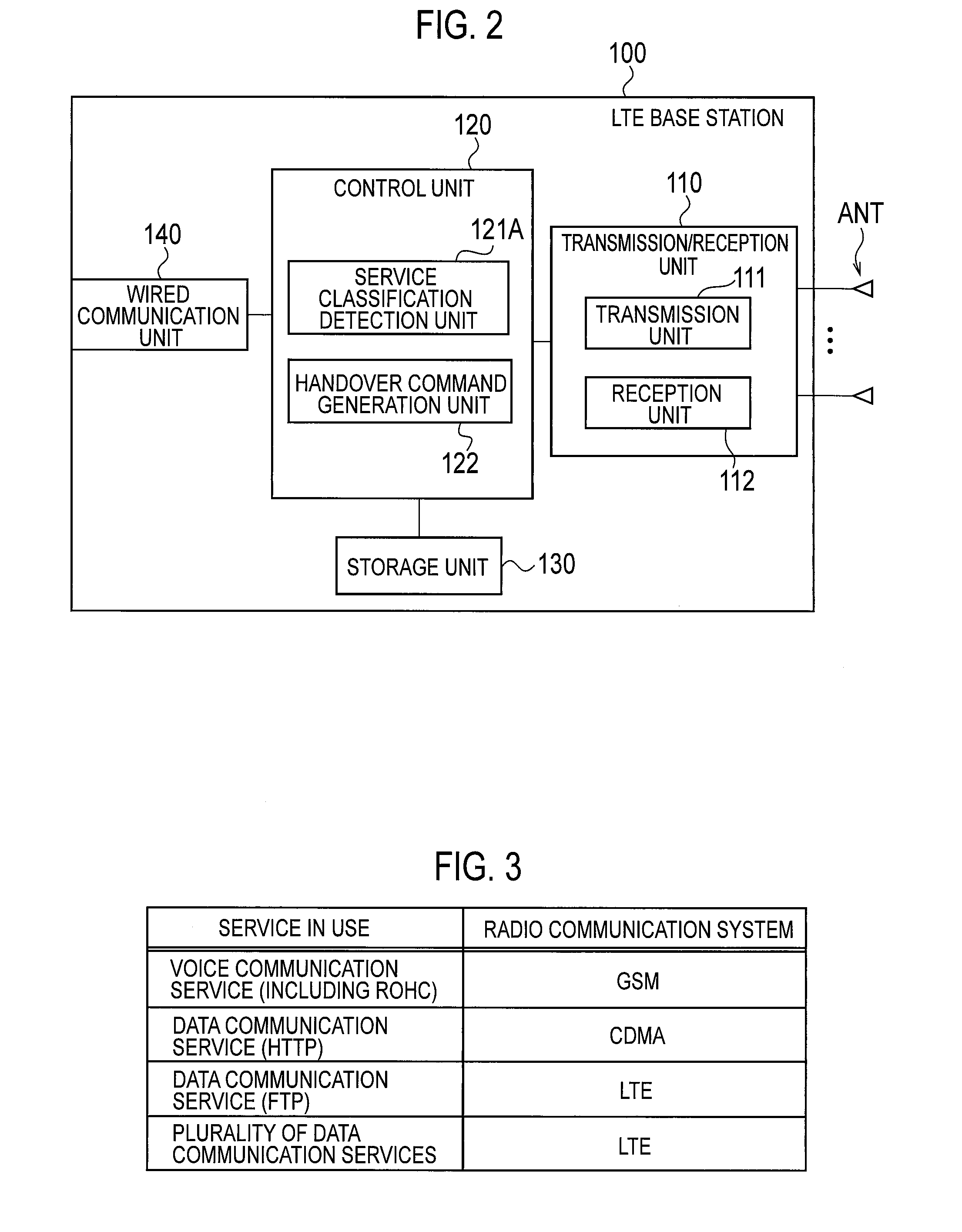
An LTE base station (100) conducts radio communication with a radio terminal which can execute a handover between a plurality of radio communication systems having different attainable communication rates. The LTE base station (100) is provided with a service detection unit (121A), which detects the classification of a communication service being used by a radio terminal, and a transmission unit (111), which sends the radio terminal a command for handover to the radio base station of a radio communication system, which handles the communication rate required for the communication service detected by the service detection unit (121A).

Description

TECHNICAL FIELD[0001]The present invention relates to a radio base station that controls handover performed by a radio terminal, and a handover control method.BACKGROUND ART[0002]In recent years, with the spread of radio communication and the diversification of a communication service, since traffic transmitted in a radio communication system is rapidly increased, it is necessary to increase a communication rate in the radio communication system. In order to cope with such a request, 3GPP (3rd Generation Partnership Project), which is a standardization project of the radio communication system, has standardized an LTE (Long Term Evolution) system regarded as the next generation (the 3.9th generation). In such a next-generation radio communication system, it is possible to achieve a higher communication rate as compared with an existing radio communication system.[0003]In the LTE system, in order to efficiently use a limited radio resource, a function called RRM (Radio Resource Manag...

Claims


Application Information

Patent Timeline
IPC IPC(8): H04W36/30
CPCH04W36/0055H04W88/06H04W36/26H04W36/14H04W36/0058H04W36/1443
Inventor MURAKAMI, KEIJIMATSUNAMI, HIROKAZUFUJITO, KYOKO
Owner KYOCERA CORP
Learn More